
Device and method for reducing generating and discharging of sintered dioxin

A sintering machine and bellows technology, applied in lighting and heating equipment, waste heat treatment, furnaces, etc., can solve the problems of high operating costs, inability to fully meet, large initial investment, etc., to reduce sintering exhaust gas and dioxin emissions. The effect of reducing the purification cost

Inactive Publication Date: 2013-09-11
MCC CAPITAL ENGINEERING & RESEARCH
View PDF4 Cites 10 Cited by
  • Summary
  • Abstract
  • Description
  • Claims
  • Application Information

AI Technical Summary

Problems solved by technology

[0003] The current dioxin prevention and control technologies in the sintering process are mainly divided into two categories. One method is to curb the generation of dioxins based on the formation mechanism of dioxins in the sintering process. This type of method mainly reduces the sintering raw materials Compounds containing benzene ring structure, chlorine sources and catalysts, etc., but this method has certain limitations and relies heavily on raw materials, which cannot fully meet the needs of modern iron ore sintering production; and Another type of method is to reduce the emission of dioxin-like substances that have been generated, mainly including activated carbon adsorption method, selective catalytic reduction method, desulfurization and denitrification method, etc. It has played a certain positive role, but they still have problems such as large initial investment, high operating cost, complex process technology and low removal efficiency to varying degrees.

Method used


Image

  • Device and method for reducing generating and discharging of sintered dioxin

Examples


Embodiment Construction

[0019] In order to have a clearer understanding of the technical features, purposes and effects of the present invention, the specific implementation manners of the present invention will now be described with reference to the accompanying drawings.

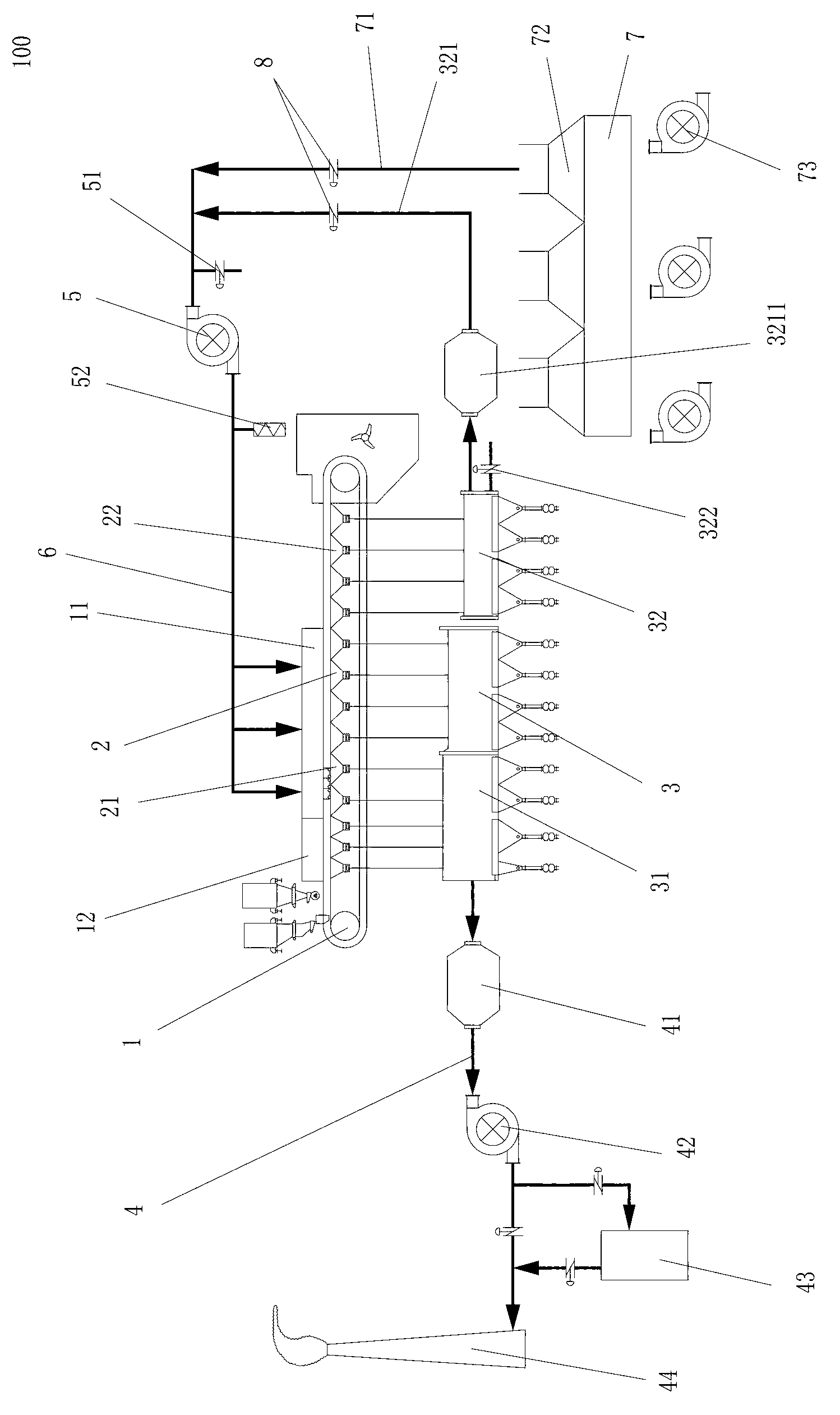
[0020] Such as figure 1 As shown, the present invention proposes a device 100 for reducing the generation and emission of sintering dioxins; the device 100 includes a sintering machine 1, a sintering machine bellows 2, and a sintering machine large flue 3 communicating with the sintering machine bellows. An igniter 12 is provided on the sintering machine; in this embodiment, the large flue 3 of the sintering machine is divided into two sections of mutually independent exhaust flue 31 and circulating flue 32; 21, the circulating flue 32 communicates with the air box 22 in the rear section of the sintering machine; the outlet of the exhaust flue 31 communicates with the exhaust pipe 4, and the exhaust gas generated in the front sec...


PUM


Abstract

The invention provides a device and method for reducing generating and discharging of sintered dioxin. The device comprises a sintering machine, sintering machine air bellows and a sintering machine large flue. The sintering machine large flue is divided into a discharging flue body and a circulating flue body which are mutually independent. The discharging flue body is communicated with a sintering machine front section air bellow, and the circulating flue is communicated with a sintering machine rear section air bellow. An outlet of the discharging flue is communicated with a discharging pipeline, the front section of the sintering machine is provided with a sealing cover, the circulating flue is connected with an inlet of a circulating fan through a waste gas circulating pipeline, and an outlet of the circulating fan is communicated with the sealing cover through a gas conveying pipeline. An annular cold air circulating pipeline in parallel connection with the waste gas circulating pipeline is communicated with the inlet of the circulating fan, and an inlet of the annular cold air circulating pipeline is communicated with an annular cold air cover of an annular cooler. According to the device and method for reducing generating and discharging of the sintered dioxin, most of the sintered dioxin in sintering waste gas is introduced into a sintering material layer and decomposed in a sintering combustion zone, and therefore generating amount and discharging amount of the sintered dioxin in the whole sintering process are reduced.

Description

technical field [0001] The invention relates to a sintering process and device in the field of metallurgy, in particular to a device and method for reducing the production and discharge of dioxins in sintering. Background technique [0002] The sintering process in the iron and steel industry is a production unit that produces more dioxin-like pollutants. The research results show that dioxins produced by sintering account for about 17.6% of the total emissions, ranking second only to waste incineration. For a long time, the domestic steel industry has not paid enough attention to the reduction of dioxin emissions. As a signatory to the Stockholm Convention on Persistent Organic Pollutants (POPs), China is obliged to take necessary means and measures to control the discharge of dioxin-like pollutants. [0003] The current dioxin prevention and control technologies in the sintering process are mainly divided into two categories. One method is to curb the generation of dioxi...

Claims


Application Information

Patent Timeline
Patent Type & Authority Applications(China)
IPC IPC(8): F27D17/00
Inventor 范振宇高景栋陈慧艳王介超胡林孙娜黄强李文琦李三军
Owner MCC CAPITAL ENGINEERING & RESEARCH
Learn More