

Miniature F-P (Fabry-Perot) cavity tunable filter and method for manufacturing same
A tuning filter, F-P technology, applied in the field of micro-electromechanical systems, can solve the problems of unfavorable production of F-P devices, no integrated process, high requirements, and achieve the effects of large deformation, large tuning range and fast response speed.
- Summary
- Abstract
- Description
- Claims
- Application Information
AI Technical Summary
Problems solved by technology
Method used
Image

Examples
preparation example Construction
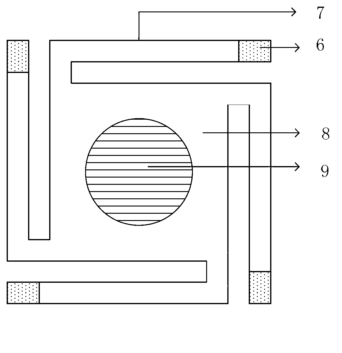
[0060] Figure 4 The top view of the prepared arrayed micro F-P cavity tunable filter provided by the embodiment of the present invention; from Figure 4 It can be concluded that the light leakage area is small, so that the fill factor of the tunable filter is high, and the optical performance of the tunable filter is good.
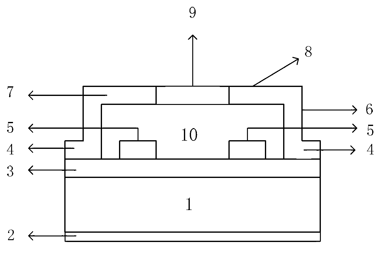
[0061] The core part of the filter unit of the miniature F-P cavity tunable filter provided by the embodiment of the present invention is a cantilever beam micro-bridge and a movable diaphragm (micro-bridge bridge deck), and the upper mirror is supported and suspended by the cantilever beam micro-bridge and the movable diaphragm. Above the lower reflector, the fixed diaphragm and the movable diaphragm of the filter base are DBR. When different voltages are applied between the fixed diaphragm and the movable diaphragm, the electrostatic force generated between the two acts on the cantilever beam micro-bridge, and the Move the upper reflector downward to c...
example 1
[0096] Example 1: A 3-5um infrared F-P cavity tunable filter array based on MEMS technology is designed by using the above scheme. This filter adopts a thin-film microbridge structure, which has the advantages of large tunable range and fast response speed, and is prepared by an integrated process. Table 1 is a table of design parameters for an infrared 3-5um F-P cavity tunable filter array.
[0097]
[0098] Table 1
[0099] The specific process implementation process of the designed 3~5um infrared micro F-P cavity tunable filter array is as follows: Figure 8 As shown, the preparation method specifically includes:
[0100] (1) cleaning the substrate surface and performing surface activation treatment;
[0101] (2) prepare the first Bragg reflector 3, and coat the anti-reflection film on the other side;
[0102] (3) make the first electrode 4 and the second electrode 5 on the face coated with the first Bragg reflector 3; AZ5214 glue is spin-coated on the DBR surface to...
Embodiment 2
[0111] Embodiment 2: In the design of Scheme 1, the spectral range for mid-wave infrared detection is 3-5um. In visible light imaging, the detection spectral range is 600-800nm. It was originally not applicable to design DBR and anti-reflection coatings, and The length of the F-P cavity needs to be changed to reduce the difficulty of the fabrication process.
[0112] Table 2 Design parameter list of F-P cavity tunable filter array for detecting visible light and detecting spectral range 600-800nm
[0113]
[0114] Table 2
PUM
 Abstract
Description
Claims
Application Information