Electromagnetic deflection device for electron beam trajectory control and application thereof

A trajectory control and electromagnetic deflection technology, applied in the field of electromagnetism, can solve the problems of difficult operation, complex operation, unknown magnetic field intensity deviation, etc., to meet the processing requirements, achieve precise control, convenient and flexible installation and disassembly.

Inactive Publication Date: 2013-09-11
LANZHOU INST OF PHYSICS CHINESE ACADEMY OF SPACE TECH
View PDF12 Cites 6 Cited by
  • Summary
  • Abstract
  • Description
  • Claims
  • Application Information

AI Technical Summary

Problems solved by technology

[0004] However, the above-mentioned patents or applications still have some defects when they are used for the precise control of the electron beam trajectory. For example, CN1876889A has no magnetic field measurement and feedback control, and the resulting magnetic field strength deviation is unknown, which is unfavorable for the precise control of the electron beam; CN1007304B, CN1164157A Both CN1233346A and CN1233346A deflection control the electron beam in the cathode ray tube for imaging, and cannot be used in the electron beam processing device; CN202121855U deflection device mechanism is many and complicated, is mainly used in medical treatment, and will occupy a vacuum in the electron beam processing Most of the volume of the chamber, and it makes the operation difficult

Method used


Image

  • Electromagnetic deflection device for electron beam trajectory control and application thereof
  • Electromagnetic deflection device for electron beam trajectory control and application thereof
  • Electromagnetic deflection device for electron beam trajectory control and application thereof

Examples


Embodiment 1

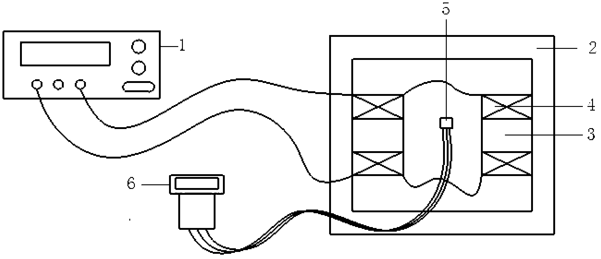
[0032] An electromagnetic deflection device for electron beam trajectory control, the device includes an excitation power supply 1, a magnetic field generating device and a Hall magnetic field detector.

[0033] Wherein, the excitation power supply 1 is a DC stabilized voltage and current power supply, the voltage is continuously adjustable from 0V to 60V, and the current is continuously adjustable from 1A to 10A; the excitation power supply 1 is placed outside the vacuum chamber of the electron beam processing device.

[0034] The magnetic field generating device includes a yoke 2, an iron core 3 and a coil 4; in order to reduce magnetic flux leakage, enhance magnetic field strength and magnetic field uniformity, the yoke 2 made of DT10 electromagnetic pure iron is in a closed circular shape; 1 pair of DT10 electromagnetic pure iron The iron core 3 made of iron is placed symmetrically inside the yoke 2, and is fixedly connected to the yoke 2 by screws; a pair of horizontally p...

Embodiment 2

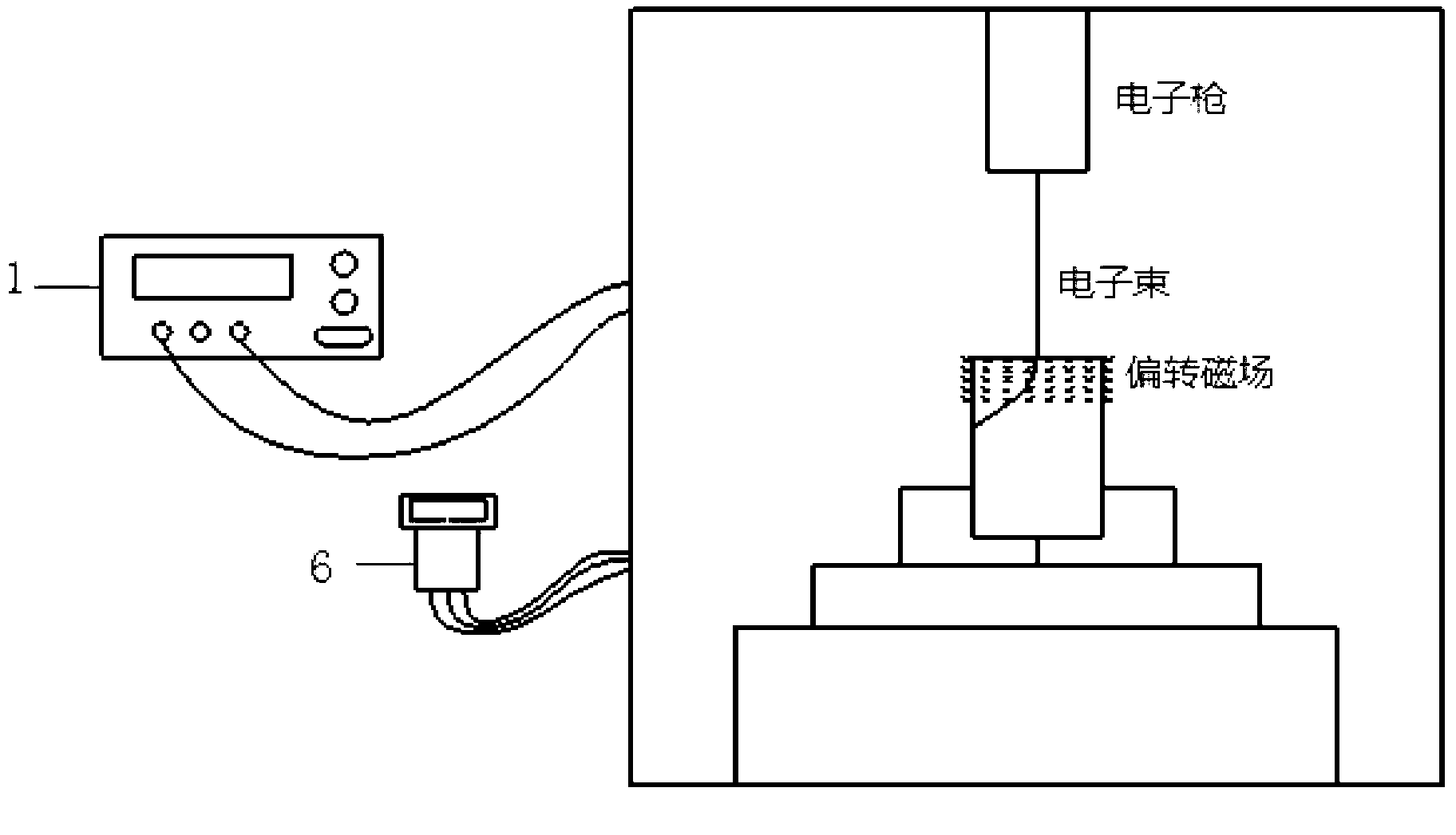
[0038] An application of the electromagnetic deflection device described in Embodiment 1, wherein the length of the air gap space is 100mm, the diameter of the coil 4=0.6mm, the number of turns of the coil 4=400, and the resistance of the coil 4 is 3Ω; the application is as follows figure 2 As shown, the specific steps are as follows:

[0039] Put a tubular part with an inner diameter of 10mm, a thickness of 1mm, and a length of 30mm on the working platform in the vacuum chamber of the electron beam processing device, located directly below the electron gun. The electron beam emitted by the electron gun flies along the axis of the tubular part in a straight line. Electron beam processing is performed on the inner surface of the tubular part, so the deflection radius of the electron beam movement trajectory needs to be deflected to 5 mm, and after deflection, it acts vertically on the inner surface of the tubular part.

[0040] According to the formula (I)

[0041] ...

Embodiment 3

[0053] An application of the electromagnetic deflection device described in Embodiment 1, wherein the length of the air gap space is 600mm, the diameter of the coil 4=0.3mm, the number of turns of the coil 4=500, and the resistance of the coil 4 is 4.5Ω; the application is as follows figure 2 As shown, the specific steps are as follows:

[0054] Put the trumpet-shaped part with the inner diameter of the small mouth of 40mm, the inner diameter of the large mouth of 50mm, the thickness of 1mm, and the length of 30mm on the working platform of the vacuum chamber of the electron beam processing device, located directly below the electron gun. When flying in a straight line in the axial direction, since the inner surface of the horn-shaped part needs to be processed with electron beams, the trajectory of the electron beam needs to be deflected with a deflection radius of 12mm, and after deflection, it acts perpendicularly on the inner surface of the horn-shaped part.

[0055] Acco...


PUM


Abstract

The invention relates to an electromagnetic deflection device for electron beam trajectory control and application of the electromagnetic deflection device and belongs to the field of electromagnetism. According to the electromagnetic deflection device for the electron beam trajectory control, an excitation power source is arranged outside a vacuum chamber of an electron beam processing device, a magnetic field generating device is arranged in the vacuum chamber, a magnet yoke is of an enclosed type, iron cores are symmetrically distributed in the magnet yoke and fixed on the magnet yoke, hollow coils are fixed on the iron cores, parts are placed in an air gap space between the iron cores, the parts are arranged under an electronic gun of the electron beam processing device, the magnetic field generating device is connected with the excitation power source through a through-wall plug which is used for coil tap, and a probe of a Hall magnetic detector is arranged in the air gap space and connected with a processing display unit arranged outside the vacuum chamber through the through-wall plug. The electromagnetic deflection device for the electron beam trajectory control is used for controlling motion trajectory of electro beams so as to meet the processing requirement of parts with special shapes, can detect and adjust a generated magnetic field in real time, enables the strength of the magnetic field to meet the processing requirement, can be directly used with an existing electron beam processing device in an integrated mode through the through-wall plug, and is wide in application range and high in economic value.

Description

technical field [0001] The present invention relates to an electromagnetic deflection device used for electron beam trajectory control and its application, in particular to an electromagnetic deflection device used for controlling the trajectory of electron beam end movement during electron beam processing, belonging to the field of electromagnetism . Background technique [0002] At present, the electron beam processing technology mainly relies on the vertical movement of the electron beam to act on the parts to be processed to realize electron beam welding and electron beam surface modification treatment. For some processed parts with special shapes, such as the inside of the cavity or the inner wall of the tubular part, since the vertical movement of the electron beam cannot directly act on the processed part, a method that can change the trajectory of the end of the electron beam is needed. and the technology and equipment for its precise control. [0003] The Chinese ...

Claims


Application Information

Patent Timeline
Patent Type & Authority Applications(China)
IPC IPC(8): H01J37/147G21K1/08
Inventor 张永和何俊王世伟刘志栋赵继鹏黄亚荣伞子栋
Owner LANZHOU INST OF PHYSICS CHINESE ACADEMY OF SPACE TECH
Why Eureka
Try Eureka