
Metamaterial antenna housing and antenna system

An antenna system and metamaterial technology, which is applied in the field of radome and antenna system, can solve the problems that the mechanical performance of the radome and high wave transmittance cannot be taken into account, the radiation efficiency and gain of the antenna are reduced, and the electromagnetic performance of the antenna is affected, and the loss is small. , Good wave-transmitting performance, small reflection effect

Inactive Publication Date: 2013-09-11
KUANG CHI INNOVATIVE TECH
View PDF3 Cites 0 Cited by
  • Summary
  • Abstract
  • Description
  • Claims
  • Application Information

AI Technical Summary

Problems solved by technology

Although materials with low dielectric constant and loss tangent and high mechanical strength are mostly used in the manufacture of radomes, such as fiberglass, epoxy resin, ABS and UPVC and other polymers, they still cannot match the wave impedance of air. When the electromagnetic wave propagates between the air and the radome, it not only reflects, but also the radome has a large loss of electromagnetic waves, which reduces the radiation efficiency and gain of the antenna and seriously affects the electromagnetic performance of the antenna.
In addition, most of the existing radome structures are uniform single-wall structure, sandwich structure and space frame structure. Under the condition of meeting the mechanical performance requirements, the radome wall is relatively thick, and the thickness of the radome is the same as that of the radome. In this way, it is impossible to take into account the mechanical properties of the radome and the requirements of high transmittance

Method used


Image

  • Metamaterial antenna housing and antenna system
  • Metamaterial antenna housing and antenna system
  • Metamaterial antenna housing and antenna system

Examples


Embodiment Construction

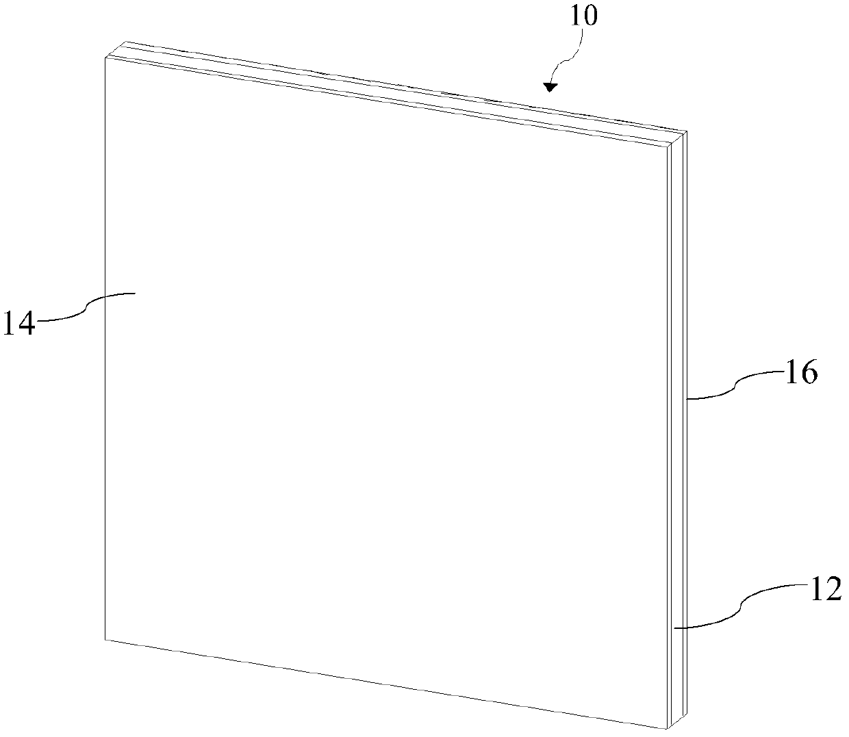
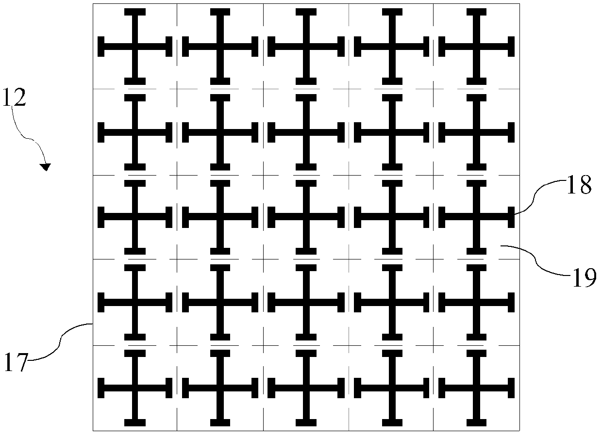
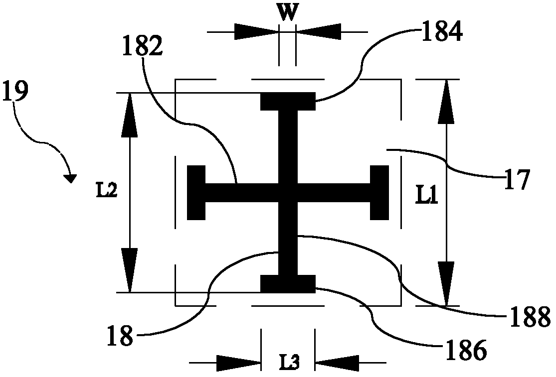
[0027] Such as figure 1 and figure 2 As shown, the metamaterial radome 10 of the present invention includes a metamaterial layer 12 and two protective layers 14 and 16 respectively covering two opposite surfaces of the metamaterial layer 12 . The metamaterial layer 12 includes a dielectric substrate 17 and a plurality of metal microstructures 18 attached to two opposite surfaces of the dielectric substrate 17 and covered by corresponding protective layers 14, 16, such as figure 2 Patterns in the grid formed by dashed lines. Wherein, the plurality of metal microstructures 18 are periodically arranged, that is, the plurality of metal microstructures 18 are periodically arranged on two opposite surfaces of the dielectric substrate 17 and are protected by the two Layers 14, 16 are protected. Every two metal microstructures 18 at corresponding positions on two opposite surfaces of the dielectric substrate 17 form a pair, and the geometry and size of each pair of metal microstr...


PUM


Abstract

The invention relates to a metamaterial antenna housing which is provided with a metamaterial layer. The metamaterial layer comprises a dielectric substrate and a plurality of metal micro-structures attached to the two opposite surfaces of the dielectric substrate. Every two metal micro-structures arranged at the corresponding positions of the two opposite surfaces of the dielectric substrate form a pair. According to each pair of the metal micro-structures, either metal micro-structure comprises two branches which are mutually orthogonal. Each branch comprises a first metal line segment, a second metal line segment and a third metal line segment. The first metal line segments and the second metal line segments are parallel to one another and just opposite to one another. One third metal line segment is located between each first metal line segment and each second metal line segment. The third metal line segments are perpendicularly connected with the first metal line segments and the second metal line segments. One third metal line segment is connected at the middle point of each first metal line segment and each second metal line segment. The third metal line segments of the two branches are perpendicularly intersected at the middle points of the third metal line segments. The metal micro-structures on one surface are overlapped with the metal micro-structures on the other surface, and therefore the metamaterial antenna housing has good wave-transparent performance. The invention further provides an antenna system.

Description

technical field [0001] The present invention relates to a radome and an antenna system, more specifically, to a radome and an antenna system made of newly designed metamaterials. Background technique [0002] In the antenna system, it is often necessary to use a radome to cover the antenna to protect the antenna from the influence of the harsh external environment. In this way, when the antenna sends and receives electromagnetic waves, the electromagnetic waves must pass through the radome. Although materials with low dielectric constant and loss tangent and high mechanical strength are mostly used in the manufacture of radomes, such as fiberglass, epoxy resin, ABS and UPVC and other polymers, they still cannot match the wave impedance of air. When the electromagnetic wave propagates between the air and the radome, it will not only be reflected, but also the radome will have a large loss of electromagnetic waves, thereby reducing the radiation efficiency and gain of the ante...

Claims


Application Information

Patent Timeline
Patent Type & Authority Applications(China)
IPC IPC(8): H01Q1/42H01Q15/02
Inventor 刘若鹏赵治亚方小伟王海莲易翔
Owner KUANG CHI INNOVATIVE TECH
Learn More