Wireless energy transmission system

A wireless energy transmission and magnetic resonance technology, applied in electromagnetic wave systems, electrical components, circuit devices, etc., can solve the problems of large overall volume of metamaterials, large microstructure size, difficult application, etc., to achieve long energy transmission distance and improve safety. performance, the effect of reducing the impact on the environment

Inactive Publication Date: 2013-09-11
KUANG CHI INNOVATIVE TECH
View PDF3 Cites 9 Cited by
  • Summary
  • Abstract
  • Description
  • Claims
  • Application Information

AI Technical Summary

Problems solved by technology

[0006] In the existing negative magnetic permeability artificial materials, a single artificial microstructure (generally called cell) is a single split ring structure or a derivative structure of a split ring, including a square structure, a circular structure or a polygon

Method used


Image

  • Wireless energy transmission system
  • Wireless energy transmission system
  • Wireless energy transmission system

Examples


Embodiment 1

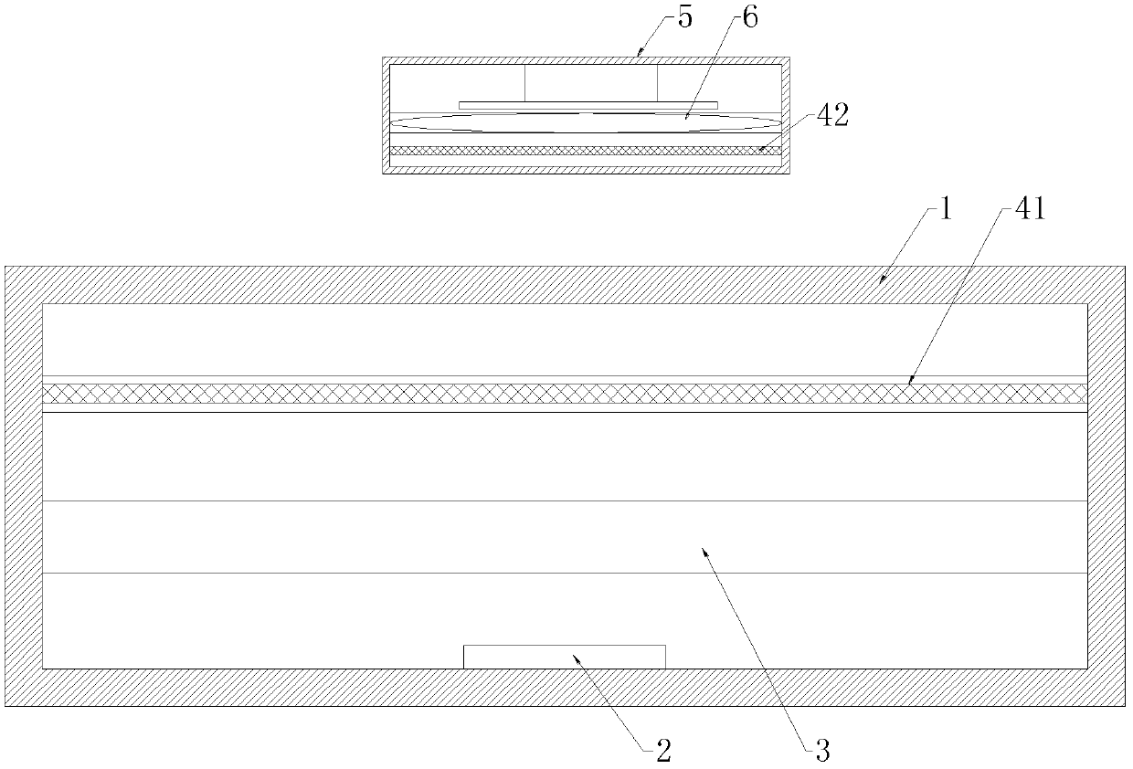
[0023] A kind of wireless energy transmission system, its system structural diagram sees attached figure 1 , including a magnetic resonance transmitting end device and a magnetic resonance receiving end device arranged in a load device, the magnetic resonance transmitting end device includes a device housing 1, a power supply module 2, a magnetic resonance transmitting module 3 and a first metamaterial 41, the first metamaterial 41 is arranged in parallel at the rear end of the magnetic resonance transmitting module 3, and a magnetic resonance receiving end device is arranged in the load device 5, and the magnetic resonance receiving end device includes a second metamaterial 42 and a magnetic resonance receiving module 6, and the second metamaterial 42 is fixedly arranged At the front end of the magnetic resonance receiving module 6, energy transfer is performed between the magnetic resonance transmitting module 3 and the magnetic resonance receiving module 6 through coupling o...

Embodiment 2

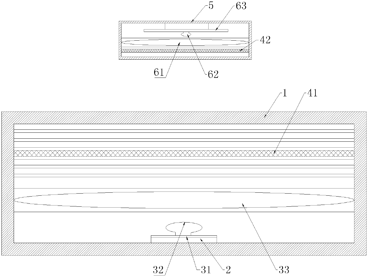
[0027] A kind of wireless energy transmission system, its system structural diagram sees attached figure 2 , including a magnetic resonance transmitting end device and a magnetic resonance receiving end device arranged in a load device, the magnetic resonance transmitting end device includes a device housing 1, a power module 2, a magnetic field resonance excitation circuit 31, a transmitting antenna 32, a magnetic resonance transmitting coil 33 and The first metamaterial 41, the first metamaterial 41 is arranged in parallel at the rear end of the magnetic resonance transmitting coil 33, and the magnetic resonance receiving end device is arranged in the load device 5, and the magnetic resonance receiving end device includes a second metamaterial 42, a magnetic resonance receiving end device The coil 61, the receiving antenna 62 and the receiving circuit 63, the second metamaterial 42 is fixedly arranged on the front end of the magnetic resonance receiving coil 61, and the magn...


PUM


Abstract

The invention provides a wireless energy transmission system. A first metamaterial is fixedly installed at the rear end of a magnetic resonance transmitting module, a second metamaterial is fixedly installed at the front end of a magnetic resonance receiving module, both the first metamaterial and the second metamaterial have negative magnetic conductivity, and therefore efficiency of energy transmission of the whole wireless energy transmission system is improved. As for the whole wireless energy transmission system, the distance of energy transmission is long, equipment at the receiving end does not need to be attached to the transmitting end, energy transmission can be achieved, the degree of using freedom of the loading equipment at the receiving end is improved greatly, and convenience is brought to users. According to the design of the metamaterials, microstructures of the metamaterials are designed to be multiply-nested split resonant rings or derived structures of the split resonant rings in a multiple winding mode. On one hand, the resonant frequency of the metamaterials can be regulated by means of the number of turns of a winding; on the other hand, the resonant frequency can be greatly reduced, influences, on the environment, from the wireless energy transmission system can be reduced, and safety performance is improved.

Description

technical field [0001] The invention relates to the field of wireless energy transmission, in particular to a wireless energy transmission system based on the principle of magnetic resonance. Background technique [0002] At present, wireless energy transmission technology is mainly based on three principles, namely electromagnetic induction, magnetic resonance and radiation. The basic feature of electromagnetic induction (non-contact inductive) power transmission circuit is the separation of primary and secondary circuits. There is a gap between it and the secondary circuit, which is connected by magnetic field coupling induction. The characteristics of the electromagnetic induction type are: there is a large air gap, so that the primary and secondary sides have no electrical contact, which makes up for the inherent defects of the traditional contact type electric energy; however, the existence of a large air gap also makes the magnetic flux leakage of the system comparable...

Claims


Application Information

Patent Timeline
IPC IPC(8): H02J17/00H02J50/12
Inventor 刘若鹏赵治亚郭洁洪运南
Owner KUANG CHI INNOVATIVE TECH
Why Eureka
Try Eureka