Supercharge Your Innovation With Domain-Expert AI Agents!

Vector control method for single current sensor

A vector control and sensor technology, applied in the field of vector control, can solve problems such as the inability to realize current decoupling transformation, and achieve the effect of improving reliability

Inactive Publication Date: 2013-09-11
HARBIN INST OF TECH
View PDF2 Cites 19 Cited by
  • Summary
  • Abstract
  • Description
  • Claims
  • Application Information

AI Technical Summary

Problems solved by technology

[0004] The purpose of the present invention is to solve the problem that the traditional vector control method cannot realize the decoupling transformation of the current when the two current sensors of the current frequency converter with three current sensors fail. The present invention provides a single current sensor vector Control Method

Method used


Image

  • Vector control method for single current sensor
  • Vector control method for single current sensor
  • Vector control method for single current sensor

Examples


specific Embodiment approach 1

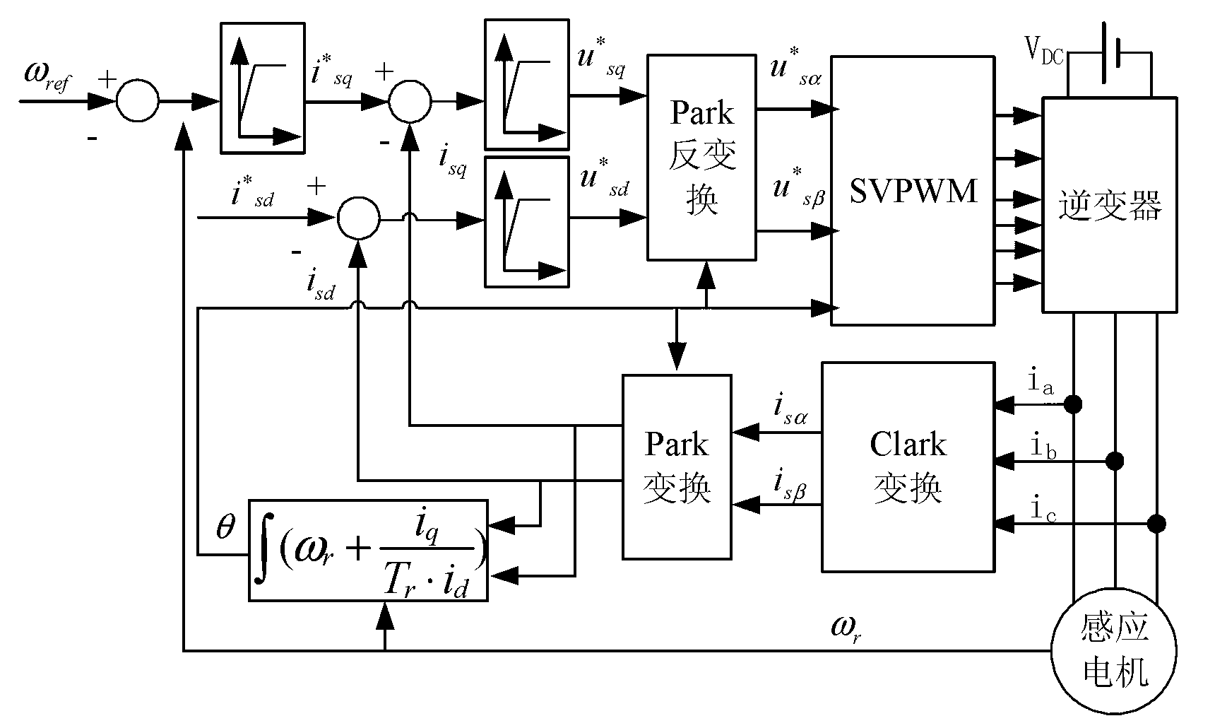
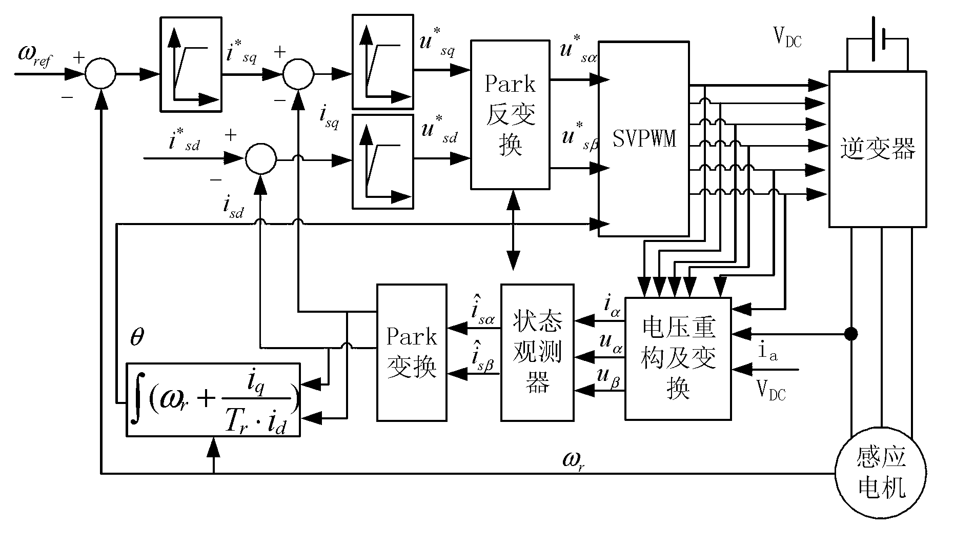
[0027] Specific implementation mode one: combine figure 1 Describe this embodiment, the single current sensor vector control method described in this embodiment,

[0028] The vector control method is realized based on the measurement of any phase current of the stator by a single current sensor. Taking the realization of the phase a current of the stator by a single current sensor as an example, the method includes the following steps:

[0029] Step 1: Use a voltage sensor to measure the DC bus voltage V DC , according to the current moment SVPWM modulation output 6 IGBT drive signals to reconstruct the stator three-phase voltage u A , u B and u C , and use the current sensor to measure the stator a-phase current i α ;

[0030] Step 2: Transform the stator three-phase voltage u obtained in Step 1 by using Clark transformation A , u B , u C and stator a-phase current i α Transform from the static three-phase coordinate system to the static αβ coordinate system to obtai...

specific Embodiment approach 2

[0045] Specific implementation mode two: combination image 3 Describe this embodiment, this embodiment is a further limitation of the single current sensor vector control method described in the first specific embodiment,

[0046] In the step 3, the stator α-axis current vector is obtained and the stator β-axis current vector The method includes the following steps:

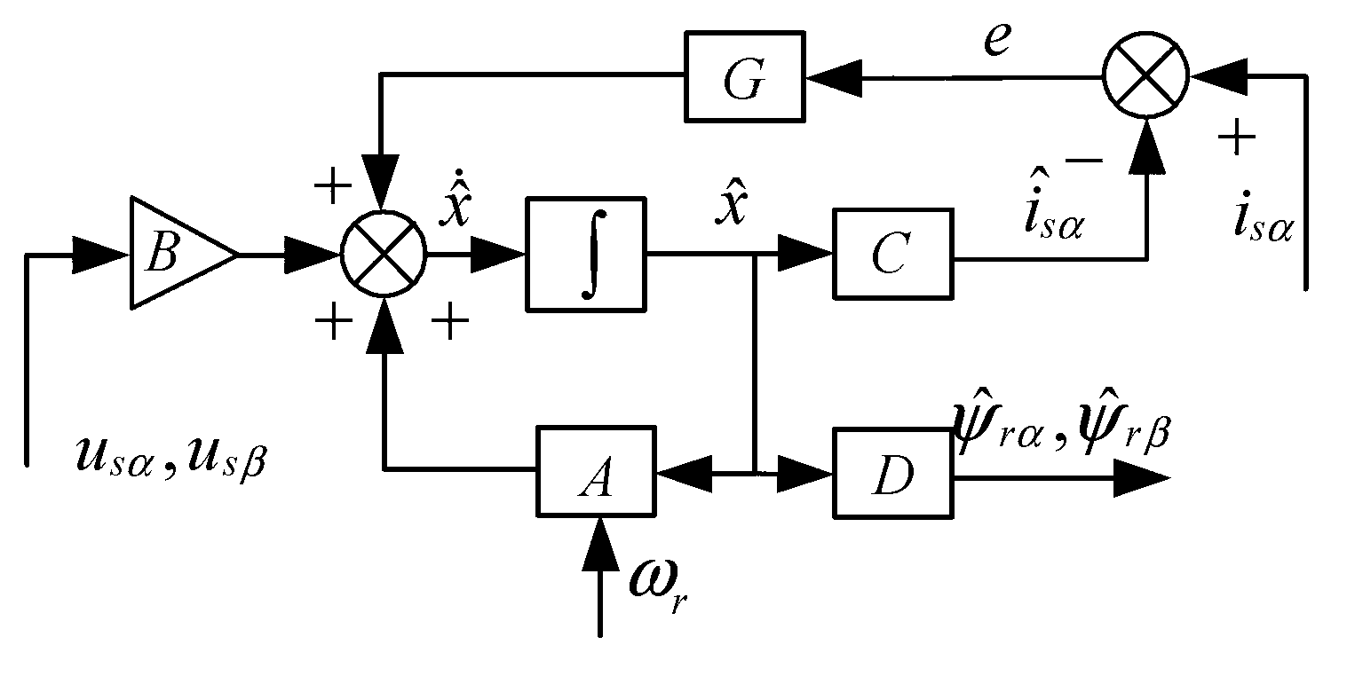
[0047] Step 31: The observed value of the stator α-axis current in the state observer and the measured stator α-axis current value Subtract to get the current error e;

[0048] Step 32: According to the formula Obtain the stator current observation state quantity derivative of Then for the derivative Integrate to obtain the stator current observation state quantity

[0049] formula:

[0050] A = a 11 0 a ...

specific Embodiment approach 3

[0068] Embodiment 3: This embodiment is a further limitation of the single current sensor vector control method described in Embodiment 1.

[0069] In the step five, the flux linkage angle θ is calculated by using the method of indirect magnetic field orientation:

[0070] θ=∫ω s dt,

[0071] In the above formula:

[0072] ω s = ω r + i sq T r · i sd

[0073] Among them, T r is the rotor time constant.

[0074] The present invention has carried out the experiment to realize the closed-loop control of the system by using a-phase current, the rated voltage of the motor is 380V, the rated power is 1.1kW, the rated speed is 1400rpm, and the given frequency is 20Hz. The experimental results are as follows ...


PUM


Abstract

The invention relates to a vector control method, in particular to a vector control method for a single current sensor, and solves the problem, that, after two current sensors of a converter comprising three current sensors fail, current decoupling transformation cannot be achieved by the traditional vector control method. According to the method, stator current and rotor flux linkage can be measured through one current signal and stator voltage vector by a single current sensor state observer; the observed stator current is used as current feedback for closed current loop; rotating speed measured by a code disc is used as speed feedback for closed speed loop; a current loop PI regulator outputs stator voltage which is modulated by SVPWM (space vector pulse width modulation) to generate six IGBT (insulated gate bipolar transistor) drive signals; accordingly, the inverter is driven to drive a motor to operate. The vector control method for the single current sensor is applicable to fault-tolerant control after two current sensors fail.

Description

technical field [0001] The invention relates to a vector control method, in particular to a single current sensor vector control method. Background technique [0002] At present, general-purpose inverters generally use three or two current sensors to complete current sampling. When the frequency converter adopts three or two current sensors, the principle block diagram of vector control is as follows: figure 1 as shown, figure 1 Medium ω ref and ω r Respectively, the given speed and the actual speed of the motor rotor, i * sd and i * sq are respectively stator d-axis current given value and stator q-axis current given value, i sd and i sq Respectively motor stator d-axis current feedback and stator q-axis current feedback, i sα and i sβ are the measured value of the stator α-axis current and the measured value of the stator β-axis current in the stationary αβ coordinate system, respectively. from figure 1 It can be seen from the figure that the control system ad...

Claims


Application Information

Patent Timeline
Patent Type & Authority Applications(China)
IPC IPC(8): H02P21/13
Inventor 于泳朱明君于雁南王高林杨荣峰徐殿国
Owner HARBIN INST OF TECH
Features
  • R&D
  • Intellectual Property
  • Life Sciences
  • Materials
  • Tech Scout
  • Unparalleled Data Quality
  • Higher Quality Content
  • 60% Fewer Hallucinations
Learn More