Bandgap voltage reference circuitry

A reference circuit and voltage reference technology, applied in the direction of adjusting electrical variables, instruments, control/regulation systems, etc., can solve the problems of increasing test time, increasing circuit complexity, and large circuit size

Active Publication Date: 2013-09-11
TEXAS INSTR INC
View PDF7 Cites 3 Cited by
  • Summary
  • Abstract
  • Description
  • Claims
  • Application Information

AI Technical Summary

Problems solved by technology

Although it is possible to use bandgap adjustment to improve the bandgap accuracy, the result is that the circuit size will become larger and the test time will be increased due to the adjustment required
This circuit architecture also limits the maximum supply voltage (VDD) when utilizing low-voltage devices (e.g., 1.8V maximum VDS), since the PMOS devices M0, M2, M3, M4, M6, and M7 are exposed to almost the full VDD voltage level
Adding a voltage protection circuit in series with these devices will increase circuit complexity and limit operation at low VDD supply levels

Method used


Image

  • Bandgap voltage reference circuitry
  • Bandgap voltage reference circuitry

Examples


Embodiment Construction

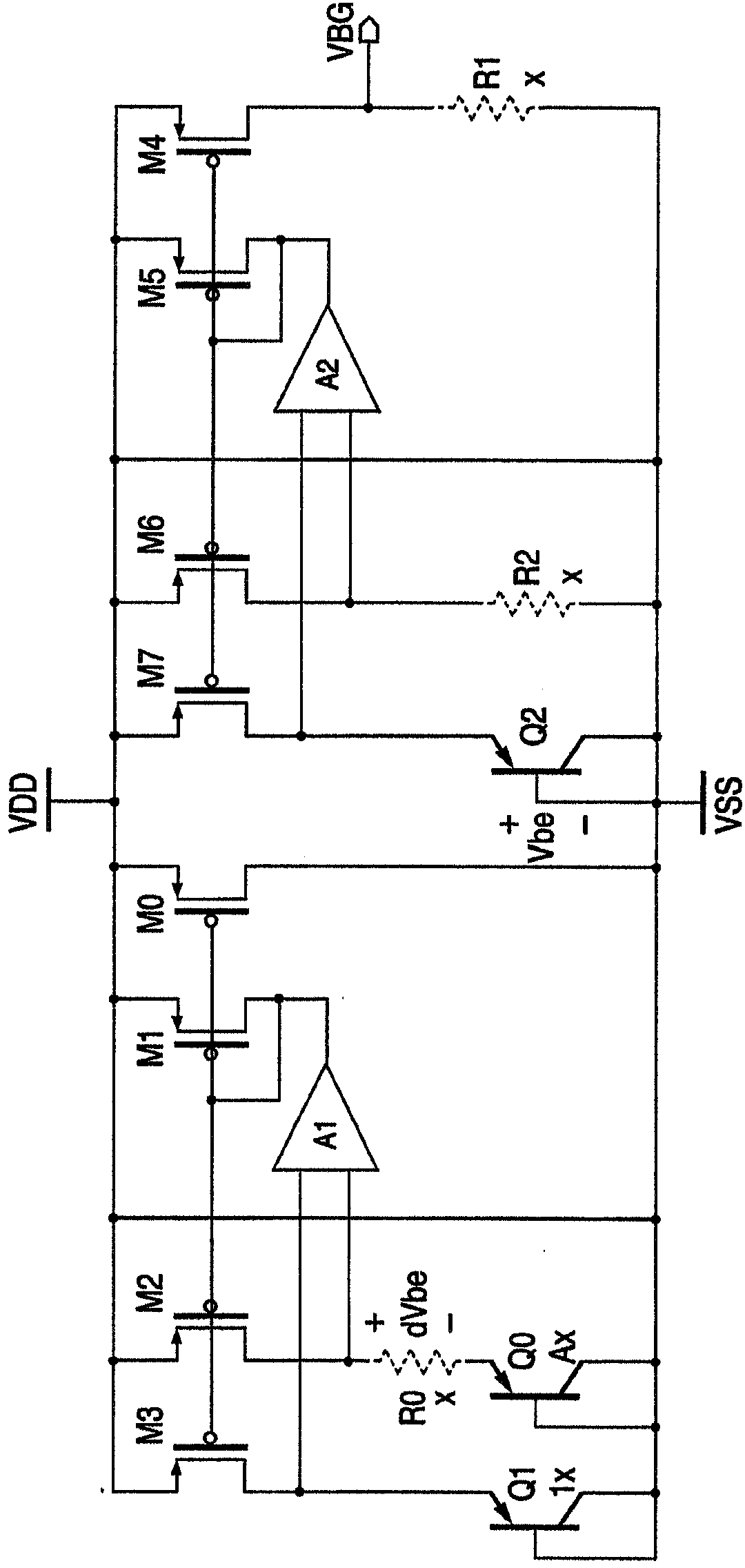
[0011] An example bandgap voltage reference circuit provides an accurate bandgap voltage reference for a wide range of supply voltages commonly used today, such as 1.5-5.5V. Such applications include portable system battery chargers with + / -1% termination voltage requirements, low dropout (LDO) regulators, switching power supplies, and other precision systems that must operate over a wide range of supply voltages. This reference circuit utilizes the Brokaw architecture, which is simple to implement and requires a low part count for optimal part matching. Further, this voltage reference circuit utilizes a low voltage threshold PMOS device (eg, VTP=0.44V, VDS=1.8V) to solve the low voltage headroom problem. Parts matching is included, and the circuit startup is reliable and operates over a wide range of supply voltages and rise times (eg, 1-10 milliseconds).

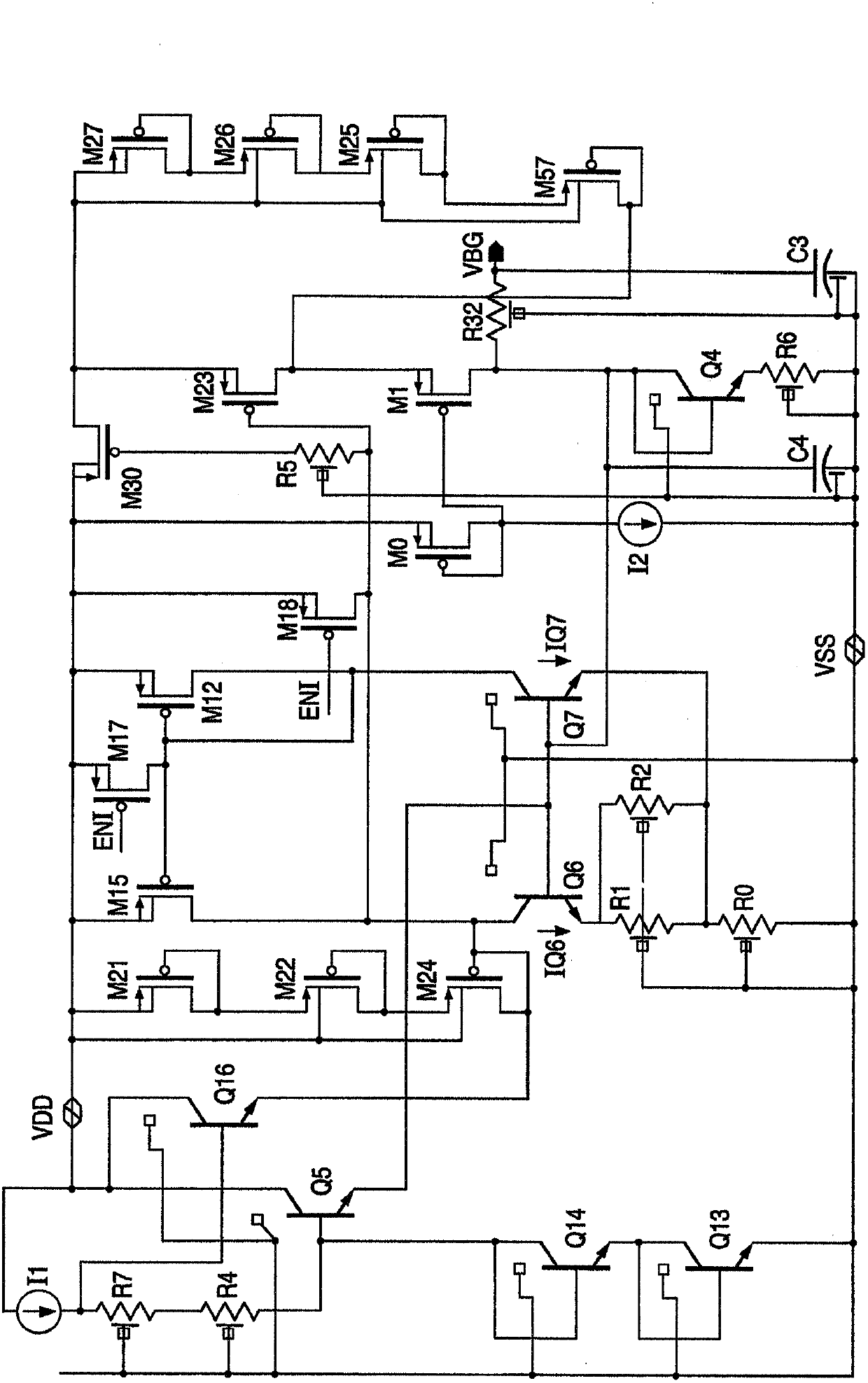
[0012] figure 2 An embodiment of an example bandgap voltage reference circuit is shown. According to the Brokaw archi...


PUM


Abstract

Bandgap voltage reference circuitry capable of operating at very low power supply voltages is disclosed. The current source for driving the core bandgap voltage reference is implemented with insulated gate field effect transistors (M12, M15) having low threshold voltages. Voltage clamp circuitry (M21, M22, M24) protects the transistors from power supply voltage variations rising above a predetermined clamp voltage. An output amplifier with output biasing circuitry having a circuit structure similar to that of the core bandgap voltage reference ensures that the bandgap reaches the intended steady state of operation.

Description

technical field [0001] The present invention relates to a bandgap voltage reference circuit, in particular to a bandgap voltage reference circuit capable of operating at a low supply voltage (eg, in the range of 1.5-5.5V). Background technique [0002] Many types of circuits and systems require reliable voltage references. In particular, such voltage references are often required to remain consistent over temperature. Perhaps the most common voltage reference circuits rely on the bandgap of silicon. Various forms of such circuits have been designed and implemented to generate a reference voltage of 1.2V, which is substantially constant over time. However, if the circuit is required to operate at a lower voltage, such as 1.5V, then the 1.2V bandgap voltage leaves only 0.3V headroom. Such a small voltage headroom is often not enough to keep the circuit working properly. [0003] Referring to Figure 1, when operating at such low supply voltages (where headroom becomes a sig...

Claims


Application Information

Patent Timeline
Patent Type & Authority Applications(China)
IPC IPC(8): G05F3/02G05F3/26G05F3/24
CPCG05F3/30
Inventor L·富E·露琛茹
Owner TEXAS INSTR INC
Why Eureka
Try Eureka