Filling structure

A filling and mounting board technology, which is applied in the fields of food, cosmetics packaging equipment, and medicine, can solve the problems that the filling structure cannot be cleaned off-line, cannot be cleaned in place, and the filling accuracy is low, so as to reduce cleaning risks and realize Versatility, the effect of avoiding pollution

Active Publication Date: 2013-09-18
上海东富龙生物试剂有限公司
View PDF9 Cites 2 Cited by
  • Summary
  • Abstract
  • Description
  • Claims
  • Application Information

AI Technical Summary

Problems solved by technology

[0005] The above three filling methods all have disadvantages. Among them, the plunger filling cannot realize cleaning in place (SIP for short in English); while the peristaltic pump filling is costly and difficult when used for multi-head filling. Large; the time pressure filling method has low accuracy for small dose filling, and its filling structure cannot realize the compatibility of off-line cleaning (abbreviated as SOP in English) and cleaning in place.
At the same time, these filling methods all have a limitation on the filling volume, which can only be adapted to a small range of filling. If it exceeds a certain range, the relevant equipment needs to be replaced.

Method used


Image

  • Filling structure
  • Filling structure

Examples


Embodiment Construction

[0019] In order to make the present invention more comprehensible, preferred embodiments are described in detail below with accompanying drawings.

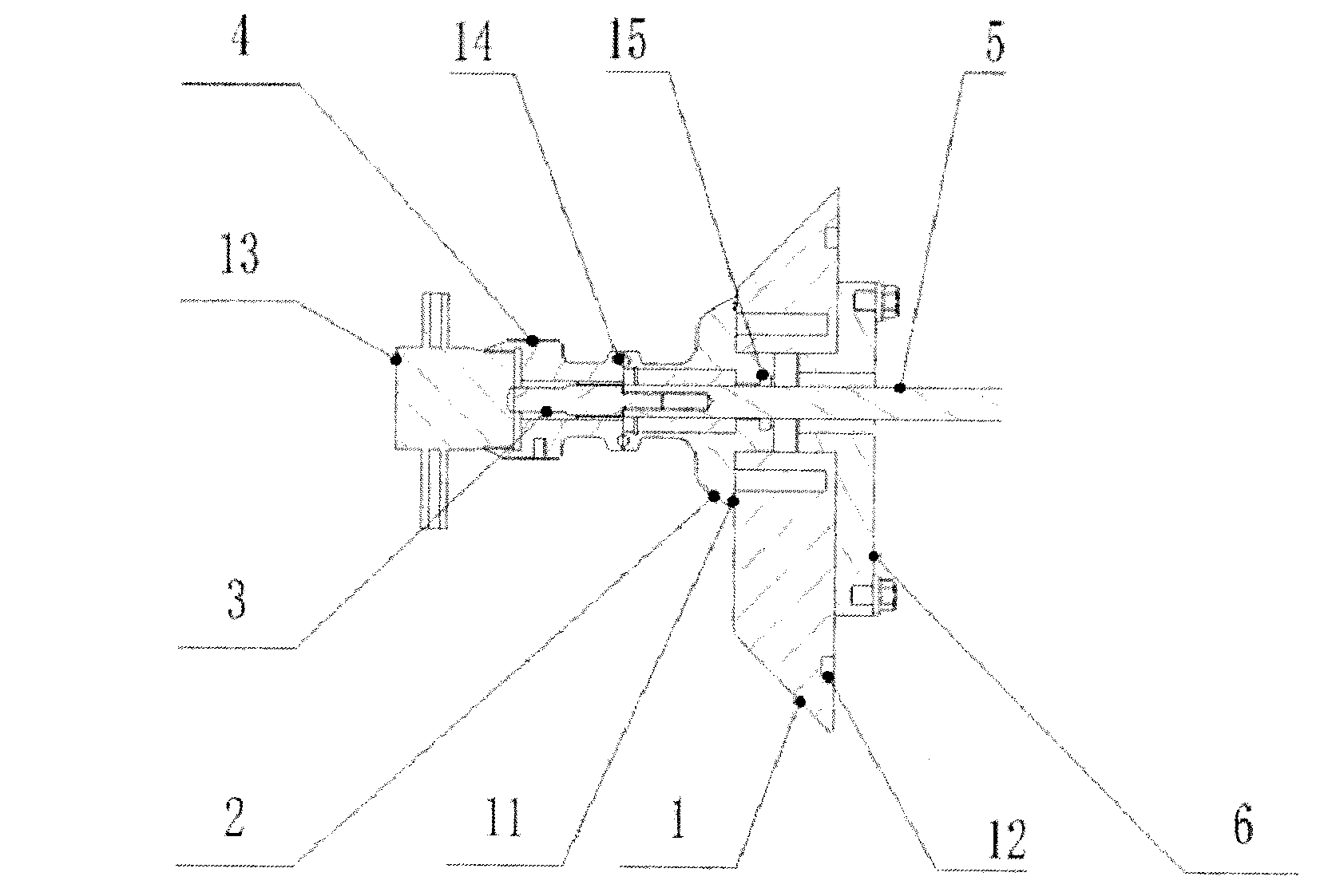
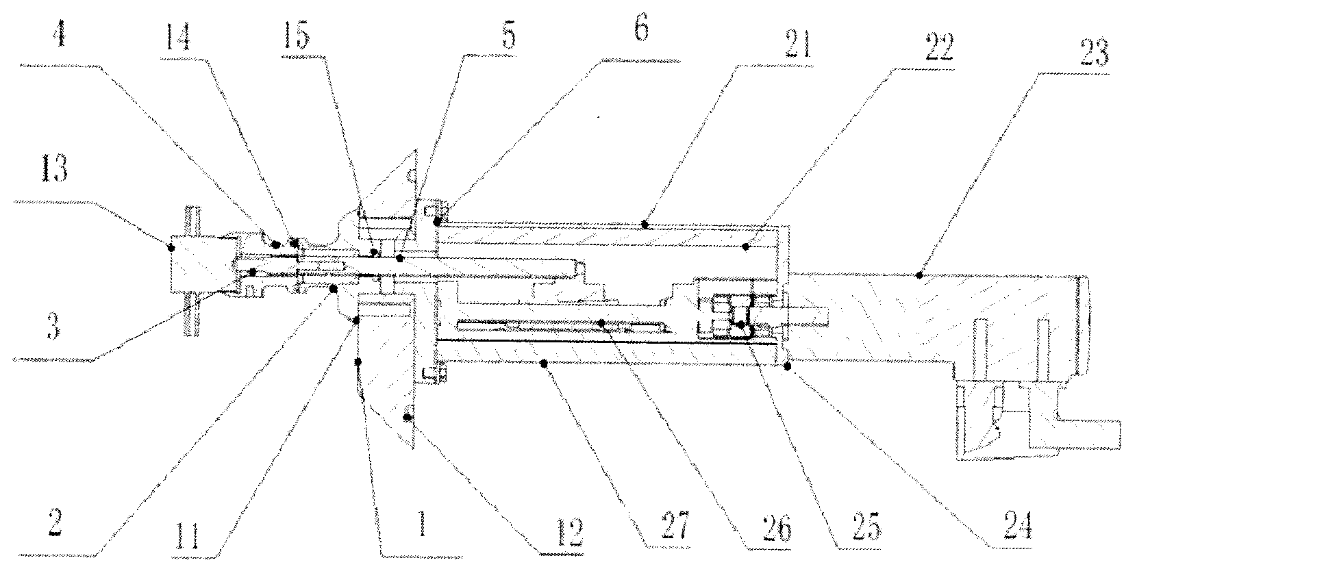
[0020] combine figure 1 and figure 2 , a filling structure disclosed in this embodiment includes a diaphragm valve 13 with a metal diaphragm. In this embodiment, the diaphragm valve 13 is a diaphragm valve with a temperature resistance of 150°C, which fully meets the requirements of SIP. The metal diaphragm has high durability and elasticity, and also includes an adapter joint 4, a push rod 3, a drive shaft 5, a mounting plate 6, a fixed base 1 and a fixed joint 2.

[0021] Mounting plate 6 is fixed on the lower support plate 27, there is a dust cover 21 above the lower support plate 27, a lead screw 26 is installed between the lower support plate 27 and the dust cover 21, and the output shaft of the servo motor 23 is connected through a high-precision coupling. The shaft device 25 is connected with the lead screw 26, and the h...


PUM


Abstract

The invention relates to a filling structure which comprises a diaphragm valve with a metal diaphragm sheet, an adapter joint which can be rapidly detached, a top rod, a driving shaft, a mounting board, a fixing base and a fixed joint. The filling structure is characterized in that the diaphragm valve is detachably fixed on the adapter joint; the adapter joint is in detachable connection with the fixed joint; the top rod is arranged inside the adapter joint and the fixed joint; the end part of the driving shaft extends into the fixed joint to be connected with the top rod; the driving shaft drives the top rod to move forwards or backwards under the driving of a driving mechanism; when the top rod moves forwards in place, the end part of the top rod is propped against the metal diaphragm sheet of the diaphragm valve so as to close the diaphragm valve; when the top rod retreats, the metal diaphragm sheet of the diaphragm valve is reset under the action of the self elasticity, then the diaphragm valve is opened. The filling structure is simple in structure, convenient to assemble and disassemble, high in filling precision and capable of realizing SOP (Standard Operation Process) / SIP (Standard Inspection Process) compatibility, no other equipment needs to be changed for a dosage of 0.1-20 ml, and the complete isolation of a filling area from a driving part is realized.

Description

technical field [0001] The invention relates to a filling structure used in a filling linkage line, belonging to the field of packaging equipment for food, medicine and cosmetics. Background technique [0002] In the existing filling structure, three filling methods are generally adopted: plunger filling, peristaltic pump filling, and time pressure filling. For example, the application number is CN200720110152, and the Chinese patent titled "Plunger Type Quantitative Filling Device" discloses a device that adopts plunger type filling, including a stepping motor fixed in the frame and driven by the stepping motor. The mechanism drives the rotating turntable. The turntable is equipped with an adjustable bottom block. The bottom block is connected to the plunger. The rotation of the turntable drives the plunger to make a reciprocating linear motion. Pipe and discharge pipe, the discharge pipe is connected to the injection nozzle, the filling material enters the inner chamber o...

Claims


Application Information

Patent Timeline
Patent Type & Authority Applications(China)
IPC IPC(8): B65B3/04
CPCB65B39/001B67C3/28B67C3/04
Inventor 郑效东
Owner 上海东富龙生物试剂有限公司
Why Eureka
Try Eureka