Underground diaphragm wall plate-type rigid joint and construction method thereof

An underground diaphragm wall and construction method technology, applied to artificial islands, water conservancy projects, underwater structures, etc., can solve the problems of cross steel plate production and complex construction process, increase seepage path, large vertical load, etc., and achieve the improvement of wall The effect of improving the integrity of the body, increasing the seepage path, and enhancing the lateral bending resistance

Active Publication Date: 2015-04-01
THE CITY VOCATIONAL COLLEGE OF JIANGSU
View PDF4 Cites 0 Cited by
  • Summary
  • Abstract
  • Description
  • Claims
  • Application Information

AI Technical Summary

Problems solved by technology

[0004] The cross steel joint can bear large vertical load, coordinate the uneven settlement of the tank section, increase the seepage path, and have better waterproof performance, but the production and construction process of the cross steel plate are relatively complicated

Method used


Image

  • Underground diaphragm wall plate-type rigid joint and construction method thereof
  • Underground diaphragm wall plate-type rigid joint and construction method thereof
  • Underground diaphragm wall plate-type rigid joint and construction method thereof

Examples


Embodiment Construction

[0031] The technical scheme of the present invention is described in detail below in conjunction with accompanying drawing:

[0032] The construction method of underground diaphragm wall rigid baffle joint of the present invention, concrete implementation operation steps are as follows:

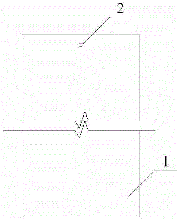
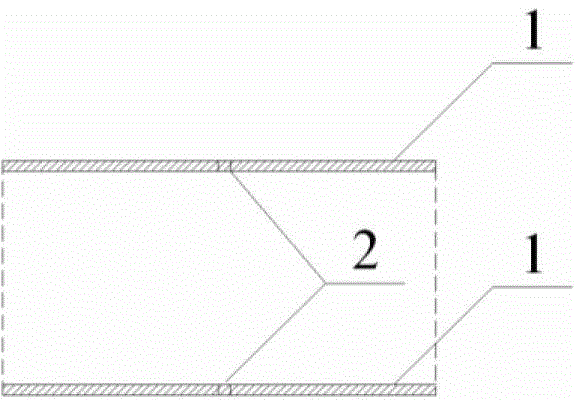
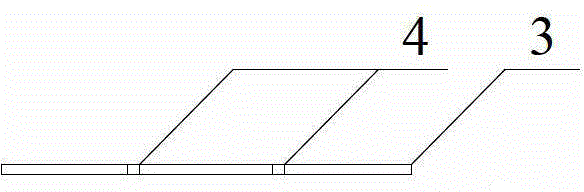
[0033] Step 1: According to the width and depth of the underground diaphragm wall, design the corresponding rigid baffle 1 and rigid base 3, including the size of the rigid baffle 1, the position and size of the connector slot 2, the size of the rigid base 3, and the reinforcement slot 4 The position and size of the locking pipe 5, the position and size of the steel bar end 6 at the bottom;

[0034] Step 2: Make rigid baffle 1, rigid bottom plate 3, and locking tube 5 according to the design;

[0035] Step 3: The fabricated rigid baffle 1 is welded to the rigid base 3 to form a rigid baffle joint 8;

[0036] Step 4: Excavate the underground diaphragm wall into grooves;

[0037] Step 5: Ass...


PUM


Abstract

The invention discloses an underground diaphragm wall rigid baffle joint and a construction method thereof, and relates to a rigid baffle joint mode and a construction method thereof. The rigid baffle joint (8) consists of two rigid baffles (1) and a rigid bottom plate (3), wherein a latch pipe (5) is arranged between the two rigid baffles (1); second connecting piece clamping grooves (7) are formed in the side surface of the latch pipe (5); first connecting piece clamping grooves (2) are formed in the side surfaces of the rigid baffles (1); the two rigid baffles (1) are connected with the latch pipe (5) by the first connecting piece clamping grooves (2) and the second connecting piece clamping grooves (7); steel bar end sockets (6) are arranged on the bottom surface of the latch pipe (5); steel bar clamping grooves (4) are formed in the rigid bottom plate (3); and the steel bar ends are fitted with the steel bar clamping grooves (4) to connect the latch pipe (5) with the rigid bottom plate (3). The rigid baffle joint is simple to design and manufacture; accurate contraposition of steel bar cages of adjacent walls is realized; the wall integrity is improved; the lateral bending resistance of the joint is improved; and a percolation path is increased.

Description

technical field [0001] The invention relates to an underground continuous wall panel type rigid joint and a construction method thereof, which belong to the technical field of geotechnical engineering foundation pit support. It is suitable for the enclosure construction of foundation pit engineering with shallow buried water level and large excavation depth, especially in soft soil and silt silt geological conditions. Background technique [0002] The underground diaphragm wall joint refers to the construction joint between the underground diaphragm wall groove section and the groove section. It can be divided into flexible joints and rigid joints. Commonly used flexible joints include: circular lock pipe joints, wave (double wave, three wave) joints, prefabricated joints and rubber waterstop joints, etc. The shear and bending resistance of flexible joints Poor, the foundation pit construction process is easily affected by groundwater and has quality problems such as leakag...

Claims


Application Information

Patent Timeline
Patent Type & Authority Patents(China)
IPC IPC(8): E02D29/16
Inventor 侯新宇嵇小雷隋宛轩薛必芳火映霞侯天宇
Owner THE CITY VOCATIONAL COLLEGE OF JIANGSU
Why Eureka
Try Eureka