Adjustable support frame used for drilling hole upward and vertically

A support frame and drilling rig technology, which is applied to drilling equipment, earthwork drilling, support devices, etc., can solve the problems that the verticality is difficult to meet the design requirements, the verticality is not easy to be guaranteed, and the stroke cannot be too long, so as to protect the health, Conducive to safe construction and convenient use

Active Publication Date: 2013-09-18
葛洲坝通信技术有限公司
View PDF7 Cites 14 Cited by
  • Summary
  • Abstract
  • Description
  • Claims
  • Application Information

AI Technical Summary

Problems solved by technology

For this type of vertical drilling, the usual construction method is to use a ladder or set up a scaffold for the operator to carry out the drilling operation. However, the disadvantage of this method is that the operator lifts the drilling rig with his arms in the air for a long time. The labor intensity is high, the construction efficiency is low, and the dust generated during drilling is likely to cause damage to the operator's eyes, which is not conducive to safe construction; moreover, the operator can only judge and control the direction of drilling based on his own experience, so when drilling When the hole is deep, its verticality is not easy to be guaranteed
[0003] Chinese patent document 102691404A discloses a percussion drill bracket used for upright drilling construction. By adopting a parallelogram bracket, upright drilling is realized. The existing problem is that the trajectory of the moving column is arc-shaped rather than straight, so the stroke cannot be too long , otherwise when drilling a deep hole, not only the verticality is difficult to meet the design requirements, but also the phenomenon of drill sticking is easy to occur

Method used


Image

  • Adjustable support frame used for drilling hole upward and vertically
  • Adjustable support frame used for drilling hole upward and vertically
  • Adjustable support frame used for drilling hole upward and vertically

Examples


Embodiment Construction

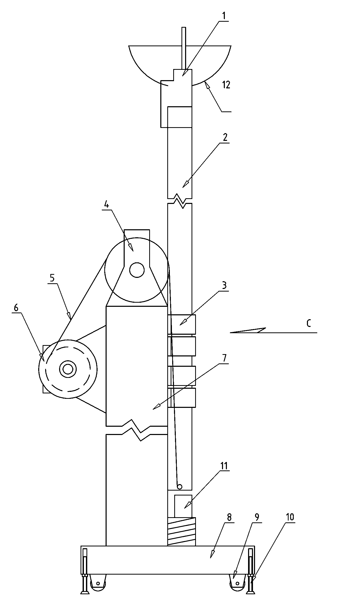
[0035] Such as figure 1 Among them, an adjustable support frame for drilling vertically upwards, including a base 8, the base in this example adopts a combined structure of a roller (9) and a base lifting device (10), wherein the roller (9) is convenient for the movement of the present invention, The base lifting device (10) is convenient for adjusting the levelness of the base 8 and provides good support. Usually, the base lifting device (10) adopts a screw structure. Base also can be the structure of tripod.

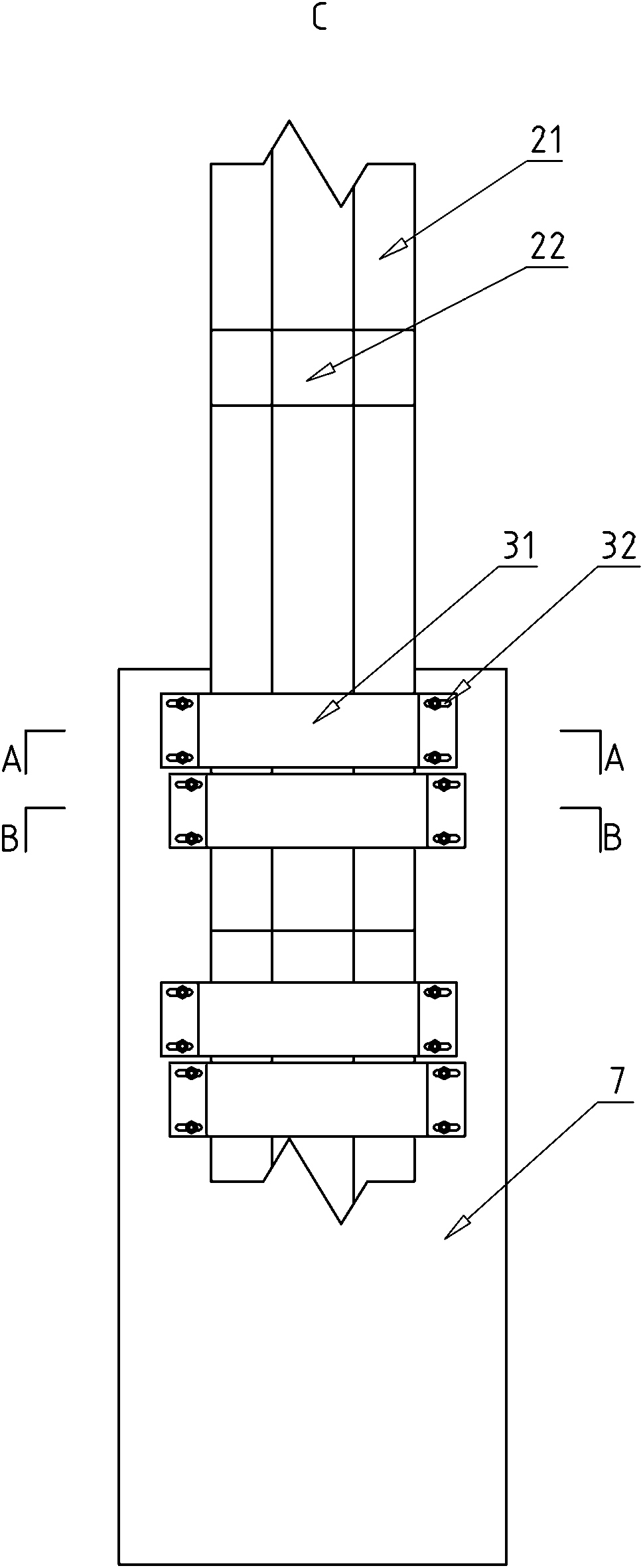
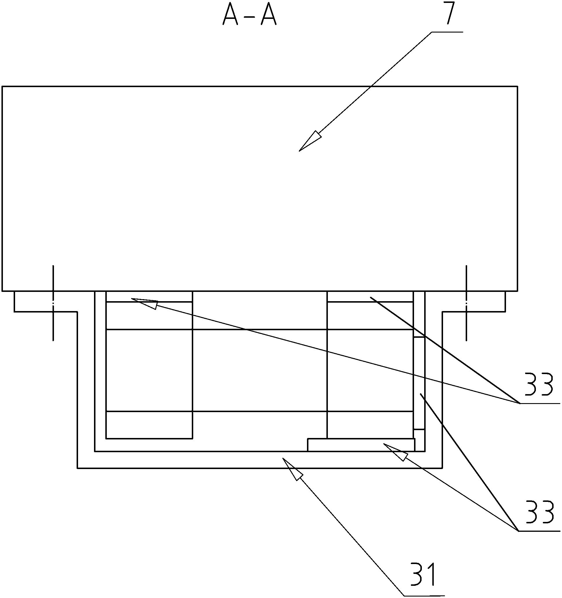
[0036] The base 8 is provided with a column 7, and the push rod 2 is connected with the slide rail 3 and the column 7 in a manner that can slide along the axis of the column 7. Hoisting device 6, the rope 5 of hoisting device 6 is connected with the bottom of push rod 2 through pulley device 4. With this structure, the construction personnel rotate the winch device 6, and the ejector rod 2 can be moved upward through the pulley device 4, and the trajectory is a strai...


PUM


Abstract

An adjustable support frame used for drilling a hole upward and vertically comprises a base, wherein an upright column is arranged on the base, a push rod is connected with the upright column through slide rails in a manner of sliding along an upright column axis; a mounting part used for mounting a drilling machine is arranged at the upper end of the push rod; a winding device is arranged on the upright column; and a rope of the winding device is connected with the lower part of the push rod through a pulley device. With the adoption of the adjustable support frame used for drilling the hole at the top, the adopted slide rails are matched with a U-shaped part provided with self-lubricating slide strips, and a pulley block is taken as lifting power, so that linear movement of the drilling machine is achieved; the vertical accuracy for drilling the hole is high, and the operation is facilitated; the slide rails which are arranged in a staggered manner are adopted, so that the frame is suitable for processing and manufacturing; and further, a structure provided with multi-row mounting racks is adopted, so that drilling for multi-row holes can be facilitated simultaneously. Besides, the adjustable support frame is convenient to use and labor-saving, reduces the labor intensity of an operator, improves the work efficiency and facilitates safe construction.

Description

technical field [0001] The invention relates to the technical field of building construction, in particular to an adjustable support frame suitable for vertically upward drilling construction on concrete floors and beam bottoms. Background technique [0002] In the construction of construction projects, it is often necessary to drill holes vertically upwards on the bottom of concrete floors and beams in order to complete the installation of other facilities. For this type of vertical drilling, the usual construction method is to use a ladder or set up a scaffold for the operator to carry out the drilling operation. However, the disadvantage of this method is that the operator lifts the drilling rig with his arms in the air for a long time. The labor intensity is high, the construction efficiency is low, and the dust generated during drilling is likely to cause damage to the operator's eyes, which is not conducive to safe construction; moreover, the operator can only judge an...

Claims


Application Information

Patent Timeline
Patent Type & Authority Applications(China)
IPC IPC(8): E21B15/00
Inventor 黄家权黎泽洲肖传勇杨富瀛李晓萍张俊霞冯晓琳
Owner 葛洲坝通信技术有限公司
Why Eureka
Try Eureka