Detonation engine

A technology of detonation engine and movable plug, which is applied to mechanical equipment, intermittent injection devices, etc., can solve the problems of unreachable detonation engine, and achieve the effects of reducing the time used, high thermal cycle efficiency, and increased rotational speed

Inactive Publication Date: 2013-09-18
谷利伟
View PDF7 Cites 10 Cited by
  • Summary
  • Abstract
  • Description
  • Claims
  • Application Information

AI Technical Summary

Problems solved by technology

But the current detonation engine is far from reaching

Method used


Image

  • Detonation engine
  • Detonation engine
  • Detonation engine

Examples


Embodiment Construction

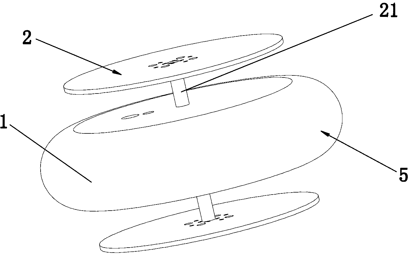
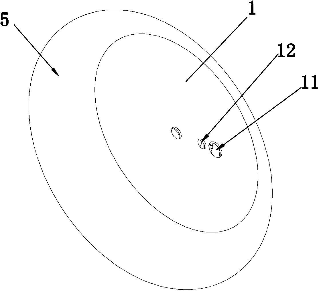
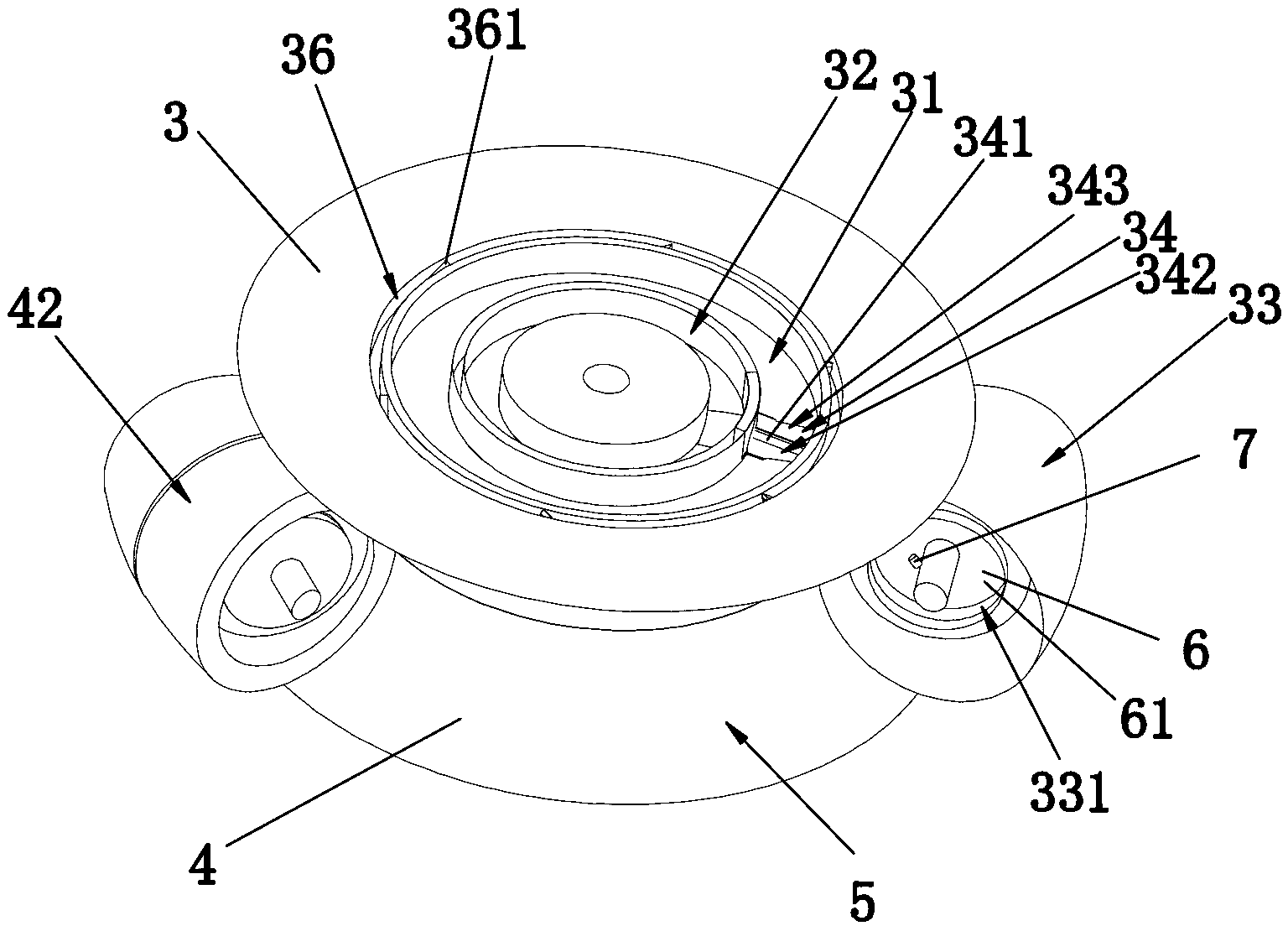
[0043] like Figure 1-Figure 14 As shown, the embodiment of the present invention is specifically a detonation engine, including a housing 1 and a power output device 2, and the housing 1 is coaxially provided with an intake rotary disk 3 and an air outlet rotary disk 4, and the intake rotary disk 3 is away from the air outlet rotary disk One side of 4 is provided with a combustible gas chamber 31 and an oxygen chamber 32, and the side of the air outlet turntable 4 facing away from the intake turntable 3 is provided with an air outlet chamber 41, and the radially outer walls of the inlet turntable 3 and the outlet turntable 4 are in contact with the shell 1. An annular channel 5 is formed between the inner side walls, and the radially outer walls of the intake rotary disk 3 and the air outlet rotary disk 4 are respectively provided with an air intake movable plug 33 and an air outlet movable plug 42 that can slide along the annular channel, and an air intake movable plug 33 and...


PUM


Abstract

The invention discloses a detonation engine which comprises a housing and a power output device, wherein two rotating discs are arranged in the housing coaxially; a fluid cavity is arranged on one side, departing from the other rotating disc, of each rotating disc; fluid holes communicated with the fluid cavities are formed in the housing; radial outside walls of the rotating discs and an inside wall of the housing form an annular channel; a movable stopper capable of sliding along the annular channel is arranged on the outside wall of each rotating disc; the movable stoppers are matched with the annular channel in a movable sealing manner, and separate the annular channel into a high-pressure cavity and a low-pressure cavity; switch through holes penetrating the movable stoppers are formed in the movable stoppers; the rotating discs are internally provided with fluid channels communicating the switch through holes with the fluid cavities of the rotating discs; and the switch through holes are internally provided with switch devices for communicating the fluid channels with the high-pressure cavity or with the low-pressure cavity. The detonation engine is great in output torque force, stable in performance, long in service life and small in size, and is suitable for more working environments; and since the structure is simplified, the detonation engine is simpler in structure.

Description

technical field [0001] The invention relates to the technical field of engines, in particular to a detonation engine. Background technique [0002] The current engine has the disadvantages of complex structure, high manufacturing cost, low efficiency and low rotational speed. In order to further improve the thermal cycle efficiency of the engine, simplify the structure of the engine and improve the performance of the engine. [0003] The pulse detonation engine is a new concept engine that uses pulse detonation waves to generate thrust. It has the advantages of high thermal cycle efficiency, simple structure, large thrust-to-weight ratio, and low unit fuel consumption rate. Since 1986, extensive experimental researches have been carried out on pulse detonation engines. At present, the pulse detonation engine researched and tested is usually closed at one end and open at the other end, plus a single Hekuo igniter, which relies on the reverse thrust generated when the deton...

Claims


Application Information

Patent Timeline
IPC IPC(8): F02K7/02F02K7/075
Inventor 谷利伟
Owner 谷利伟
Why Eureka
Try Eureka