Boiler blow down system

A boiler blowdown and regular blowdown technology, applied in the field of boiler applications, can solve the problems of water resource waste, low temperature and pressure, no longer use, etc., and achieve the effect of optimizing the process flow, increasing enterprise benefits, and increasing the amount of condensed water.

Active Publication Date: 2013-09-18
BEIJING PETROCHEM ENG
View PDF6 Cites 6 Cited by
  • Summary
  • Abstract
  • Description
  • Claims
  • Application Information

AI Technical Summary

Problems solved by technology

[0007] 3. The low-pressure exhaust steam flashed from the top of the tank is no longer used because its temperature and pressure (normal pressure) are too low, and it is directly discharged into the atmosphere
[0009] Problems in the above process settings: Regular blowdown usually uses normal pressure flash evaporation, and the condensed water at the bottom of the tank (including a large amount of circulating cooling water or industrial water used for cooling) cannot be returned to the circulating cooling water return system due to the low pressure , it can only be discharged into the nearby ditch (sewage system), causing a lot of waste of water resources
At the same time, since the boiler water contains impurities such as iron rust and precipitated slag formed by dosing treatment, the purpose of regular sewage discharge is to regularly discharge these slag and other precipitated impurities from the boiler. If it is not recycled and directly discharged into the surrounding environment through the ditch, will cause water pollution in the surrounding environment

Method used


Image

  • Boiler blow down system
  • Boiler blow down system

Examples


Embodiment Construction

[0034] The principles and features of the present invention are described below in conjunction with the accompanying drawings, and the examples given are only used to explain the present invention, and are not intended to limit the scope of the present invention.

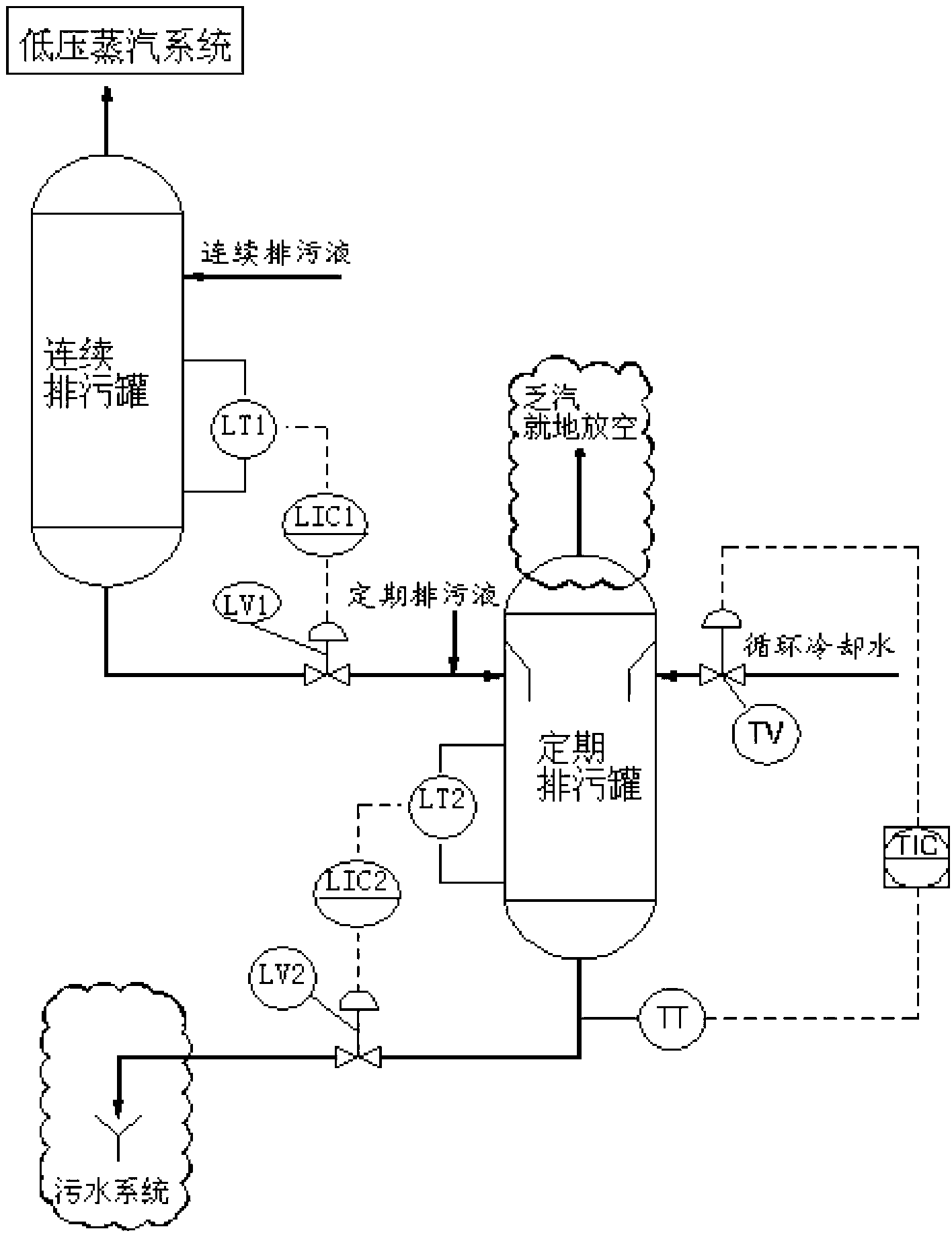
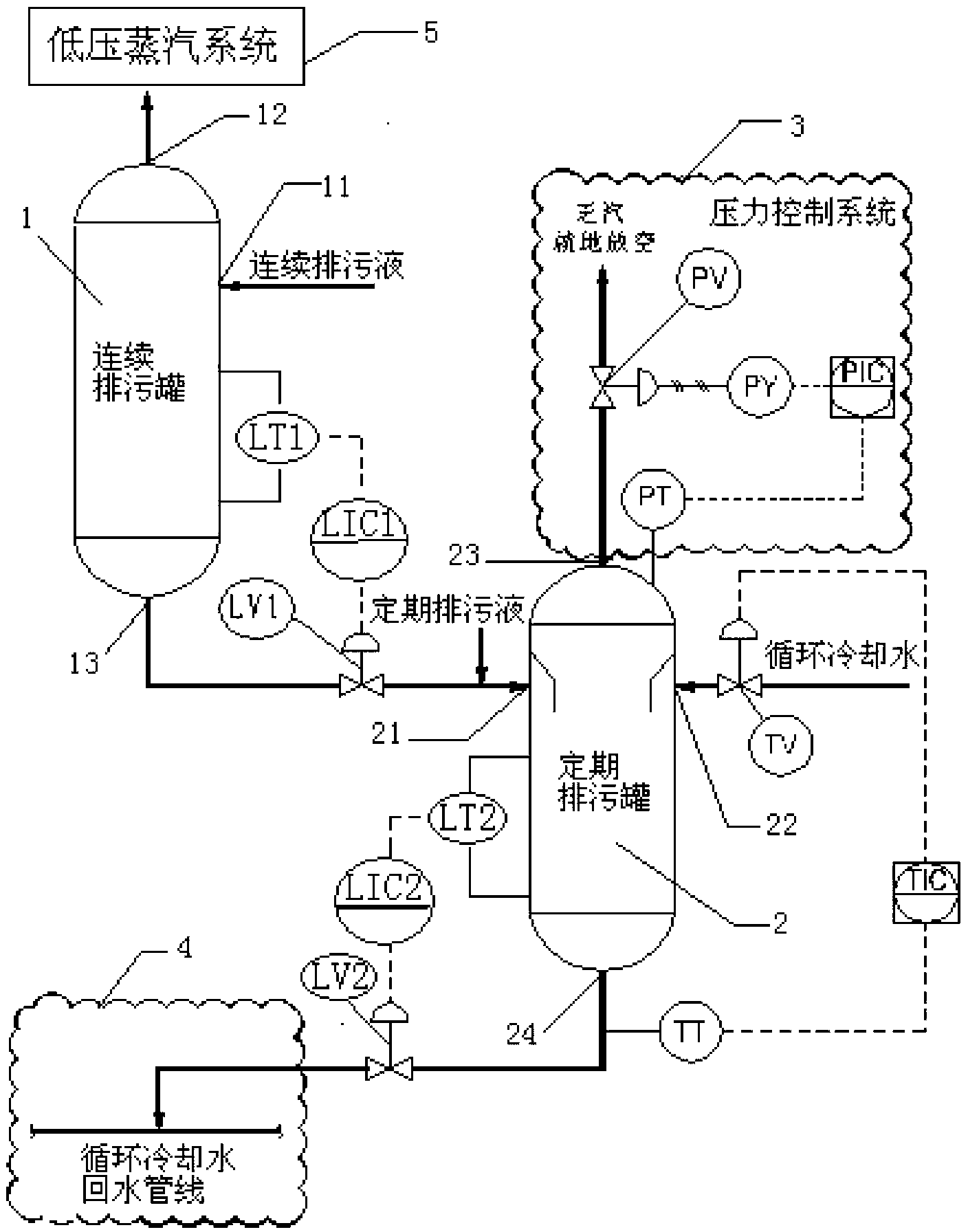
[0035] Such as figure 2 As shown, Embodiment 1 provides a boiler blowdown system, including a continuous blowdown tank 1, a regular blowdown tank 2, a pressure control system 3 and a circulating cooling water return line 4:

[0036] The continuous blowdown tank 1 is used for flash evaporation and vapor-liquid separation of the continuous blowdown liquid, and is provided with a tangential input port 11 of the continuous blowdown tank, a top output port 12 of the continuous blowdown tank and a bottom output port 13 of the continuous blowdown tank. Continuous blowdown tank. The tangential input port 11 of the continuous blowdown tank is used for inputting continuous blowdown liquid, the top output port 12 of the cont...


PUM


Abstract

The invention relates to a boiler blow down system which comprises a continuous blow down tank, a periodic blow down tank, a pressure control system and a recirculated cooling water return pipeline, wherein as for the continuous blow down tank, a tangential input port is used for inputting continuous blow down liquid, an output port at the top is used for outputting low-pressure steam, and an output port at the bottom is used for outputting bottom condensate into the periodic blow down tank; as for the periodic blow down tank, a first tangential input port is used for inputting the bottom condensate and the periodic blow down liquid of the continuous blow down tank, a second tangential input port is used for inputting recirculated cooling water, the output port at the top is used for discharging the low-pressure exhaust steam into atmosphere through the pressure control system, and the output port at the bottom is used for discharging tank bottom condensed water into the recirculated cooling water return pipeline; the pressure control system is arranged at the top of the periodic blow down tank and used for controlling the operating pressure of the periodic blow down tank and discharging low-pressure exhaust steam; and the recirculated cooling water return pipeline is arranged at the bottom of the periodic blow down tank and used for recovering tank bottom condensed water of the periodic blow down tank. The boiler blow down system can reasonably recycle the periodic blow down condensed water, which reduces water resource waste and boosts corporate profitability.

Description

technical field [0001] The invention relates to the technical field of boiler application, in particular to a boiler blowdown system capable of continuous blowdown and regular blowdown. Background technique [0002] my country's existing petroleum, chemical, steel, power station, pharmaceutical, printing and dyeing, urban heating and many other enterprises are using a large number of boilers. Due to the continuous evaporation and concentration of boiler water, the impurity content in the remaining water will become higher and higher. In order to reduce the content of salt and alkali in the pot water, it is necessary to discharge part of the concentrated sewage from the pot water frequently. Through sewage discharge, the salt content of the pot water can be reduced, avoiding the occurrence of steam and water, and ensuring the quality of the pot water and steam. When the boiler water level is too high, the water level can also be lowered by blowdown. In addition to a small am...

Claims


Application Information

Patent Timeline
Patent Type & Authority Applications(China)
IPC IPC(8): F22B37/54
Inventor 王永锋国昕王建国张兴李毅陆伟亓峰
Owner BEIJING PETROCHEM ENG
Why Eureka
Try Eureka