Ultraviolet, visible and ultraviolet prism chromatic dispersion imaging spectrometer

An imaging spectrometer and near-infrared technology, applied in the field of space remote sensing imaging spectroscopy, can solve the problems of short wavelength band and small dynamic range of detectable signals, and achieve the effect of light weight and small size

Active Publication Date: 2013-09-18
CHANGCHUN INST OF OPTICS FINE MECHANICS & PHYSICS CHINESE ACAD OF SCI
View PDF4 Cites 11 Cited by
  • Summary
  • Abstract
  • Description
  • Claims
  • Application Information

AI Technical Summary

Problems solved by technology

[0003] The invention provides an ultraviolet, visible and near-infrared prism dispersion imaging spectrometer in order to solve the problems of the existing imaging spectrometer with short band and small dynamic range of detectable signals

Method used


Image

  • Ultraviolet, visible and ultraviolet prism chromatic dispersion imaging spectrometer
  • Ultraviolet, visible and ultraviolet prism chromatic dispersion imaging spectrometer

Examples


specific Embodiment approach 1

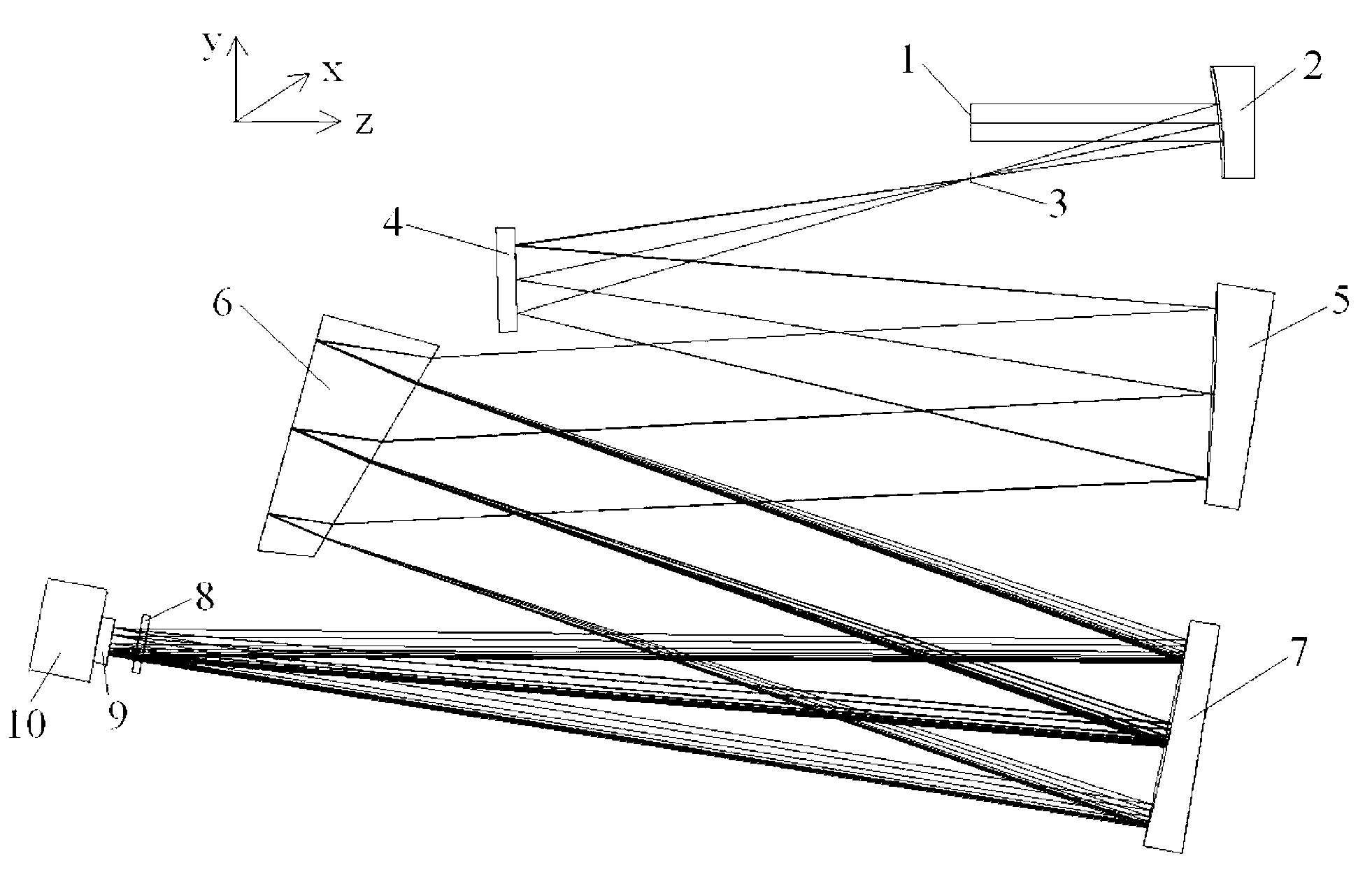
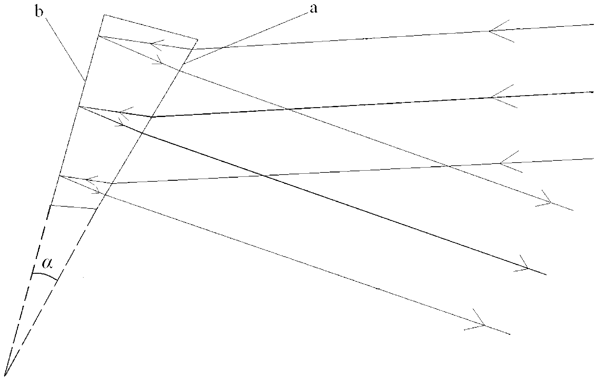
[0010] Specific implementation mode 1. Combination figure 1 and figure 2 Describe this embodiment, ultraviolet, visible, near-infrared prism dispersive imaging spectrometer, this spectrometer includes optical system, CCD detector 9 and electronic system 10, optical system includes telescopic system and spectral imaging system, telescopic system includes aperture stop 2 and a telescope 2, the spectral imaging system includes an incident slit 3, a plane folding mirror 4, a collimating mirror 5, a dispersion prism 6, an imaging mirror 7 and a sub-band attenuation filter 8. The beams of ultraviolet, visible, and near-infrared bands emitted by the target are first imaged on the incident slit 3 through the aperture stop 1 and the telescope 2, and then pass through the plane folding mirror 4, collimating mirror 5, and dispersion The prism 6, the imaging mirror 7 and the sub-band attenuation filter 8 are imaged on the CCD detector 8, and the two-dimensional spectral image is obtaine...

specific Embodiment approach 2

[0014] Specific embodiment two, combine figure 1 and figure 2 Describe this embodiment. This embodiment is the application of the ultraviolet, visible, and near-infrared prism dispersive imaging spectrometer described in Embodiment 1. The spectrometer described in Embodiment 1 is applied to ultraviolet-visible-near-infrared atmospheric remote sensing, and the working band 250-1000nm, the telescope is a single off-axis parabolic mirror, the focal length of the telescope is 120mm, the field of view is 2.4°×0.024°, the size of the entrance slit is 5mm×0.05mm, and the size of the aperture stop is Φ30mm. Atmospheric astigmatism in the ultraviolet-visible-near-infrared band is imaged on the entrance slit through the aperture diaphragm and the telescope. Both the collimating mirror and the imaging mirror are six-time off-axis aspheric mirrors, the radius of curvature of the collimating mirror is 573.51, the coefficient of the second order is -0.21077, and the coefficient of the six...


PUM


Abstract

An ultraviolet, visible and ultraviolet prism chromatic dispersion imaging spectrometer relates to the technical field of the space remote sensing imaging spectrum and solves the problems of short working wavebands and small dynamic scope of detectable signal of the current imaging spectrometer. The ultraviolet, visible and ultraviolet prism chromatic dispersion imaging spectrometer comprises a CCD (Charge Coupled Device) detector, an electronic system, a telescoping system and a spectrum imaging system; the telescoping system comprises a aperture diaphragm and a telescope; the spectrum imaging system comprises an entrance slit, a planar turning mirror, a collimating mirror, a collimating mirror, an imaging mirror and a sub-waveband attenuation optical filter. The telescoping system images one band of a target into the entrance slit; the spectrum imaging system disperses the entrance slit and images the entrance slit to the CCD detector; and the electronic system acquires and processes the image on the CCD detector. The ultraviolet, visible and ultraviolet prism chromatic dispersion imaging spectrometer has a compact structure, a small volume and a light weight, can carry out imaging spectrum detection for the target of the signal within a big ultraviolet-visible-ultraviolet scope. The ultraviolet, visible and ultraviolet prism chromatic dispersion imaging spectrometer is applied to the field of spaceflight and aerial remote sensing.

Description

technical field [0001] The invention relates to the technical field of space remote sensing imaging spectrum, in particular to an ultraviolet, visible and near-infrared prism dispersion imaging spectrometer. Background technique [0002] Imaging spectrometer is a new type of space optical remote sensing instrument that can obtain spectral information and image information at the same time. It is being used more and more widely in the fields of land and resources survey, ocean and atmospheric remote sensing. However, the working bands of existing imaging spectrometers are mostly concentrated in the visible or near-infrared bands, and the working bands are short, so the types of material components that can be detected are limited to a certain extent. In the visible or near-infrared band, the target radiation signal strength has little change, which is 10 3 The order of magnitude is within the dynamic range of the CCD detector itself, so visible or near-infrared imaging spect...

Claims


Application Information

Patent Timeline
Patent Type & Authority Applications(China)
IPC IPC(8): G01J3/28
Inventor 薛庆生王淑荣
Owner CHANGCHUN INST OF OPTICS FINE MECHANICS & PHYSICS CHINESE ACAD OF SCI
Why Eureka
Try Eureka