Device and method for measuring optical Brillouin gain spectrum by aid of rectangular spectrum probe light

A technology of Brillouin gain spectrum and optical fiber measurement, which is applied in the fields of interference spectroscopy and spectrum investigation, which can solve the problems of unfavorable long-distance measurement and achieve the effect of shortening the measurement time

Inactive Publication Date: 2015-01-28
HARBIN UNIV OF SCI & TECH
View PDF4 Cites 0 Cited by
  • Summary
  • Abstract
  • Description
  • Claims
  • Application Information

AI Technical Summary

Problems solved by technology

[0004] The present invention aims to solve the problem that the ASE light source is used as the detection light in the existing Brillouin gain spectrum testing method, which is not conducive to long-distance measurement, and provides a device for measuring the optical fiber Brillouin gain spectrum using the rectangular spectrum detection light and methods

Method used


Image

  • Device and method for measuring optical Brillouin gain spectrum by aid of rectangular spectrum probe light
  • Device and method for measuring optical Brillouin gain spectrum by aid of rectangular spectrum probe light
  • Device and method for measuring optical Brillouin gain spectrum by aid of rectangular spectrum probe light

Examples


specific Embodiment approach 1

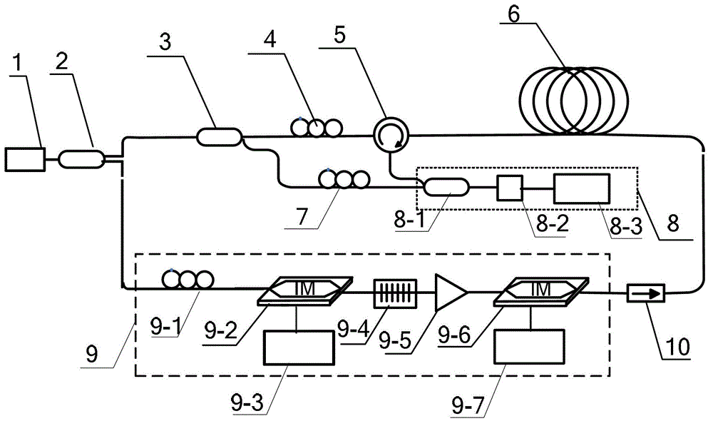
[0021] Specific implementation mode 1: the following combination figure 1 with figure 2 To explain this embodiment, the device for measuring the gain spectrum of fiber Brillouin using rectangular spectrum probe light in this embodiment includes a fiber laser 1, and it also includes a first fiber splitter 2, a second fiber splitter 3, The first polarization controller 4, the fiber circulator 5, the fiber to be tested 6, the second polarization controller 7, the heterodyne measuring instrument 8, the rectangular spectrum detection light source 9, and the fiber isolator 10,

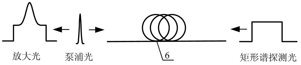
[0022] The laser light output by the fiber laser 1 is divided into two beams by the first fiber splitter 2, the first beam is incident on the second fiber splitter 3, and the second beam is incident on the input port of the rectangular spectrum detection light source 9.

[0023] The laser light emitted from the first output port of the second fiber splitter 3 enters the first port of the fiber circulator 5 throug...

specific Embodiment approach 2

[0026] Specific implementation manner 2: the following combination figure 2 This embodiment will be described. This embodiment will further explain the first embodiment. The heterodyne measuring instrument 8 in this embodiment is composed of an optical fiber combiner 8-1, a photodetector 8-2 and a spectrum analyzer 8-3.

[0027] The first laser input port of the heterodyne measuring instrument 8 is the first laser input port of the optical fiber combiner 8-1, and the second laser input port of the heterodyne measuring instrument 8 is the second laser input of the optical fiber combiner 8-1 Port, the optical signal output end of the fiber optic combiner 8-1 is connected to the optical signal input end of the photodetector 8-2, and the electrical signal output end of the photodetector 8-2 is connected to the electrical signal input end of the spectrum analyzer 8-3 .

[0028] In this embodiment, except for the circuit connection between the photodetector 8-2 and the spectrum analyzer...

specific Embodiment approach 3

[0029] Specific implementation manner three: the following combination figure 2 This embodiment will be described. This embodiment will further explain the first or second embodiment. The rectangular-spectrum detection light source 9 in this embodiment is the third polarization controller 9-1, the first intensity modulator 9-2, and the microwave generator 9 -3. It is composed of fiber grating filter 9-4, fiber amplifier 9-5, second intensity modulator 9-6 and arbitrary waveform signal generator 9-7,

[0030] The input port of the rectangular spectrum detection light source 9 is the input port of the third polarization controller 9-1. The optical signal output end of the third polarization controller 9-1 is connected to the optical signal input end of the first intensity modulator 9-2. The electrical signal input end of an intensity modulator 9-2 is connected to the electrical signal output end of the microwave generator 9-3, and the optical signal output end of the first intensit...


PUM


Abstract

The invention relates to a device and a method for measuring optical Brillouin gain spectrum by aid of rectangular spectrum probe light, belongs to the field of optical Brillouin gain spectrum measuring technology, and solves the problem that ASE (airborne search equipment) source is taken as probe light in the existing measuring methods of Brillouin gain spectrum, and the measuring methods are bad for measurement in long distance. The device comprises a fiber laser, a first optical fiber branching device, a second optical fiber branching device, a first polarization controller, an optical circulator, optical fiber to be measured, a second polarization controller, a heterodyne gauge, rectangular spectrum probe light source and an optical isolator. Bandwidth of rectangular spectrum can be flexibly adjusted according to difference of optical materials to be measured. Power of rectangular spectrum probe light close to Stokes frequency shift can be adjusted, and rectangular spectrum probe light can meet requirement of long-range detection. The device and the method for measuring optical Brillouin gain spectrum by aid of rectangular spectrum probe light are used for detecting optical Brillouin gain spectrum.

Description

Technical field [0001] The invention relates to a device and a method for measuring optical fiber Brillouin gain spectrum using rectangular spectrum probe light, and belongs to the technical field of optical fiber Brillouin gain spectrum measurement. Background technique [0002] The Brillouin gain spectrum contains important information such as Brillouin frequency shift, line width, and gain envelope. It is widely used in distributed optical fiber sensing, filtering and amplification of weak signals, and Brillouin lidar detection. In order to obtain a Brillouin gain spectrum with a higher signal-to-noise ratio SNR, the pump-detection method is usually used for measurement, that is, a tunable laser or microwave generator is used to control an electro-optic intensity modulator to generate Stokes frequency-shifted probe light. It interacts with the oppositely propagating pump light in the Brillouin amplifier medium to realize the energy or power transfer of the pump light to the pr...

Claims


Application Information

Patent Timeline
Patent Type & Authority Patents(China)
IPC IPC(8): G01J3/45
Inventor 高玮刘胜男胡晓博毕雅凤史光耀张洪英
Owner HARBIN UNIV OF SCI & TECH
Why Eureka
Try Eureka