
Digital dimming control system for light-emitting diode (LED) and method thereof

A control system, digital dimming technology, applied in energy-saving control technology, light source, electric light source, etc., can solve the problems of complex system, high cost, poor reliability, etc., achieve simple circuit structure, ensure stability, and realize constant current output Effect

Active Publication Date: 2013-09-18
SOUTHEAST UNIV
View PDF4 Cites 4 Cited by
  • Summary
  • Abstract
  • Description
  • Claims
  • Application Information

AI Technical Summary

Problems solved by technology

In the dimming control system, according to the input control signal and the feedback signal, the purpose of dimming the LED is achieved by changing the current flowing through the output LED. To achieve this goal, complex digital dimming systems are usually required Advanced A / D, D / A conversion circuit, complex system, high cost, poor reliability

Method used


Image

  • Digital dimming control system for light-emitting diode (LED) and method thereof
  • Digital dimming control system for light-emitting diode (LED) and method thereof
  • Digital dimming control system for light-emitting diode (LED) and method thereof

Examples


Embodiment Construction

[0031] Below in conjunction with accompanying drawing, the technical scheme of invention is described in detail:

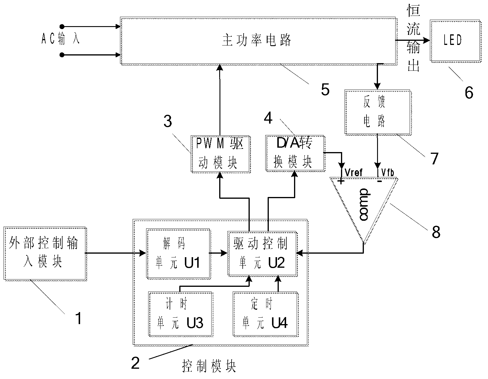
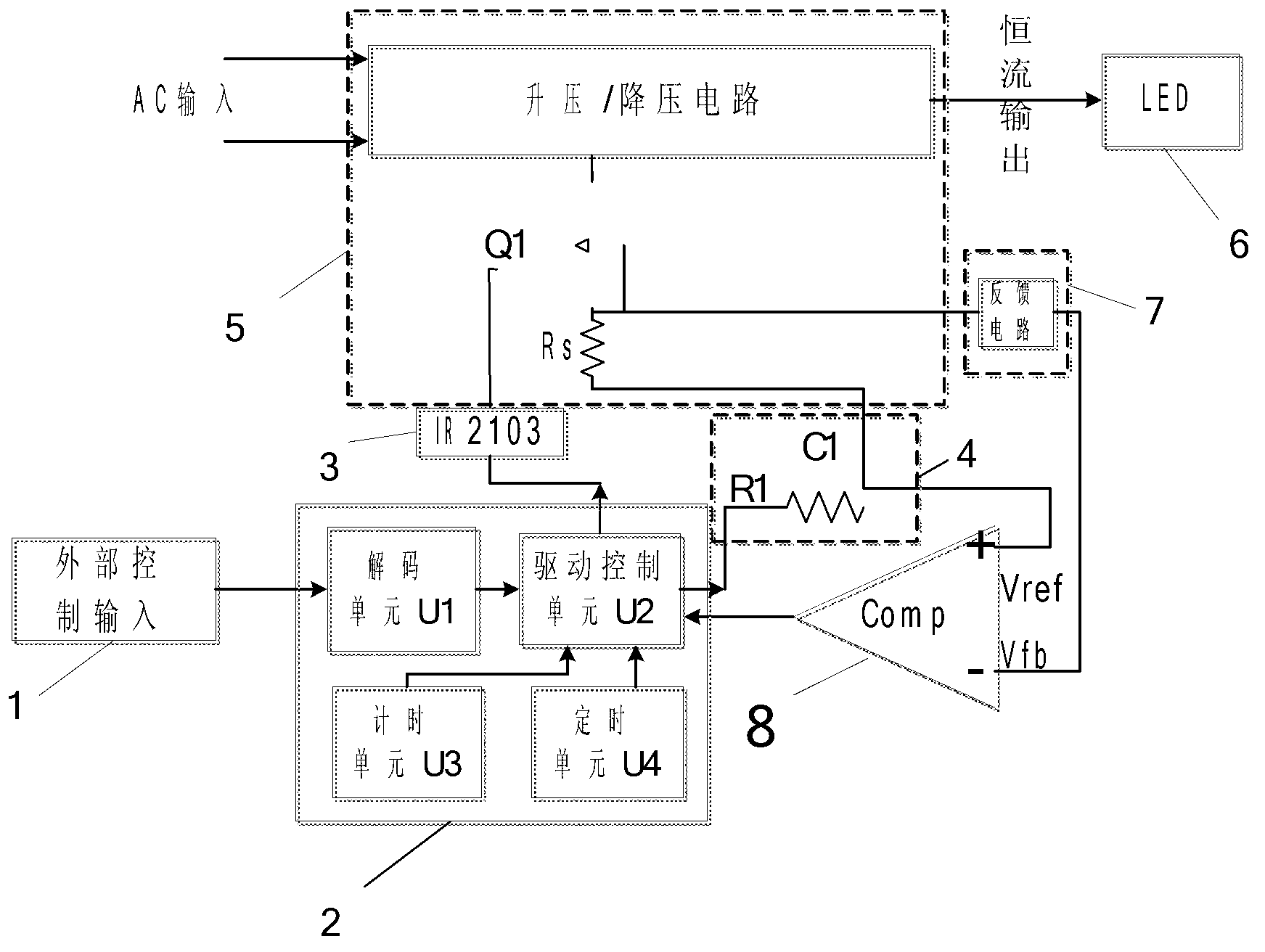
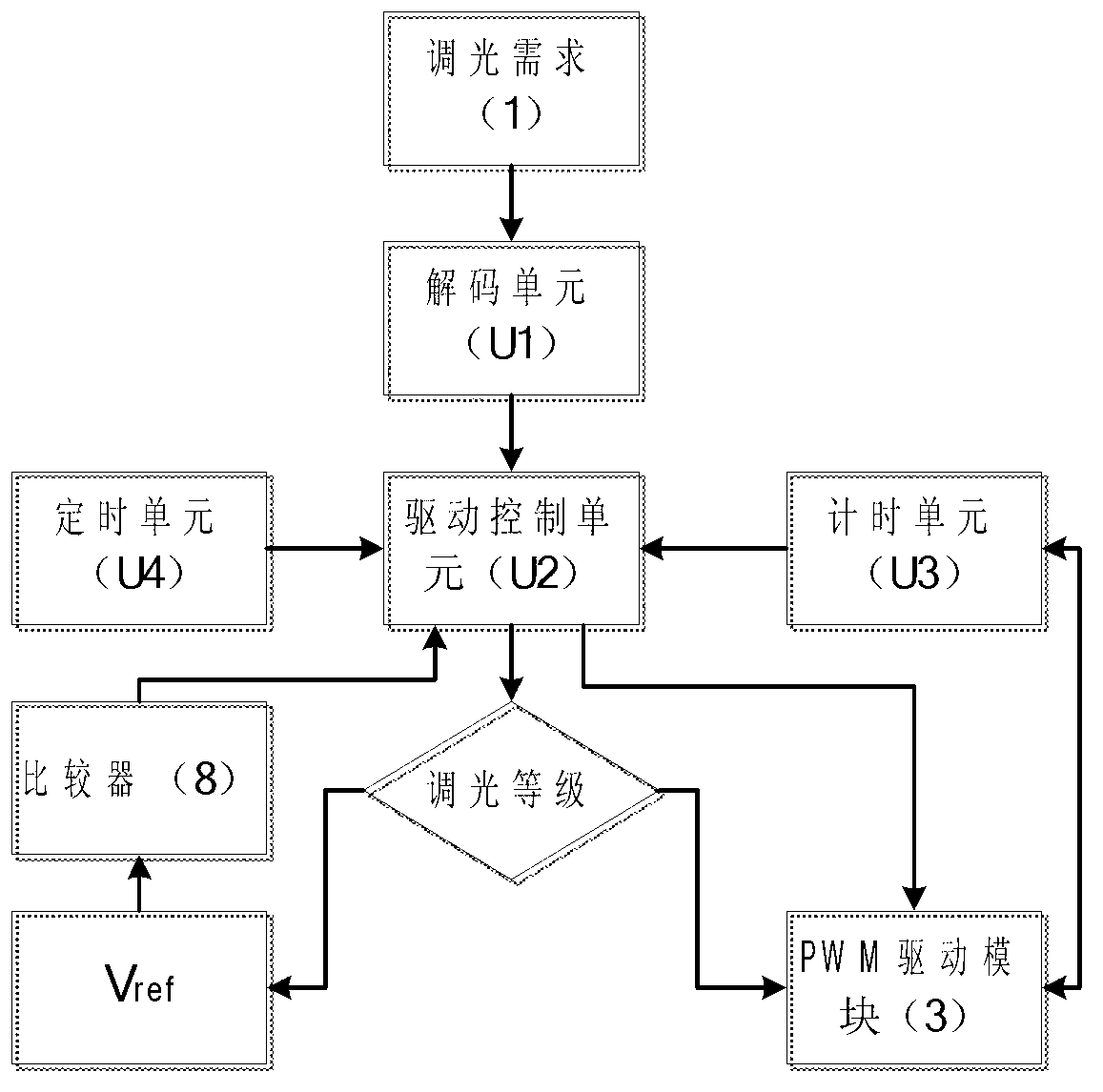
[0032] Such as figure 1As shown, the dimming control system of the present invention includes an external control input module 1, a control module 2, a PWM drive module 3, a D / A conversion module 4, a main power circuit 5, an LED load 6, a feedback circuit 7, and a comparator 8. All parts of the circuit (module) use known circuits (modules) except those described in the claims and the specification. The control module 2 includes a decoding unit U1, which is used to obtain the dimming information of the external control input module 1; a drive control unit U2, which is used to realize the corresponding control of the PWM drive module according to the demand, according to the control signal of the external control input module 1 and the timing unit U3 1. The timing information of the timing unit U4 and the feedback information of the comparator 8 control the duty r...


PUM


Abstract

A digital dimming control system for a light-emitting diode (LED) comprises a main power circuit and an LED load, is provided with an external control input module and comprises a control module, a pulse width modulation (PWM) driving module, a digital to analog (D / A) conversion module, a feedback circuit and a comparator, wherein the control module comprises decoding unit, a driving control unit, a time keeping unit and a timing unit. The control module adjusts switching time of PWM driving waveforms by controlling the PWM driving module according to the requirements of the external control input module; on one hand, the driving control unit changes a voltage reference value Vref of the input end of the comparator through the D / A conversion module, and on the other hand, the driving control unit controls connection of PWM signals. The time keeping unit is used for calculating connection time of the PWM during every period, the timing unit is used for determining the switching time of the PWM, the driving control unit guarantees constancy of a switching period of the PWM driving module through the timing unit, and by comparing time Treal obtained by the time keeping unit and storage time Tstatic inside the driving control unit, the driving control unit adjusts the connection time of the PWM and achieves corresponding protection.

Description

technical field [0001] The invention relates to an LED dimming control system, in particular to an LED digital dimming control system and a method thereof. Background technique [0002] The dimming control system has developed from the original analog dimming and semi-digital dimming system to a mature full-digital dimming system. With the development of semiconductor technology, the application of full-digital dimming is also more extensive. In LED lighting, since the brightness of a light-emitting diode is determined by the current flowing through the diode, in the digital dimming control system, the power tube switch is controlled by controlling the duty cycle of the digital dimming signal, and then the average current flowing through the light-emitting diode is controlled. current, so as to achieve the purpose of dimming. In the dimming control system, according to the input control signal and the feedback signal, the purpose of dimming the LED is achieved by changing t...

Claims


Application Information

Patent Timeline
Patent Type & Authority Applications(China)
IPC IPC(8): H05B37/02
CPCY02B20/40
Inventor 钱钦松王炎宝汪国军张太之王永平孙伟锋陆生礼时龙兴
Owner SOUTHEAST UNIV
Learn More