Organic solvent exhaust gas recovery and purification plant
A waste gas recovery and organic solvent technology, applied in chemical instruments and methods, dispersed particle separation, separation methods, etc., can solve the problems that resources cannot be recycled, achieve high equipment utilization, reduce pollution, and improve efficiency.
- Summary
- Abstract
- Description
- Claims
- Application Information
AI Technical Summary
Problems solved by technology
Method used
Image

Examples
Embodiment 1
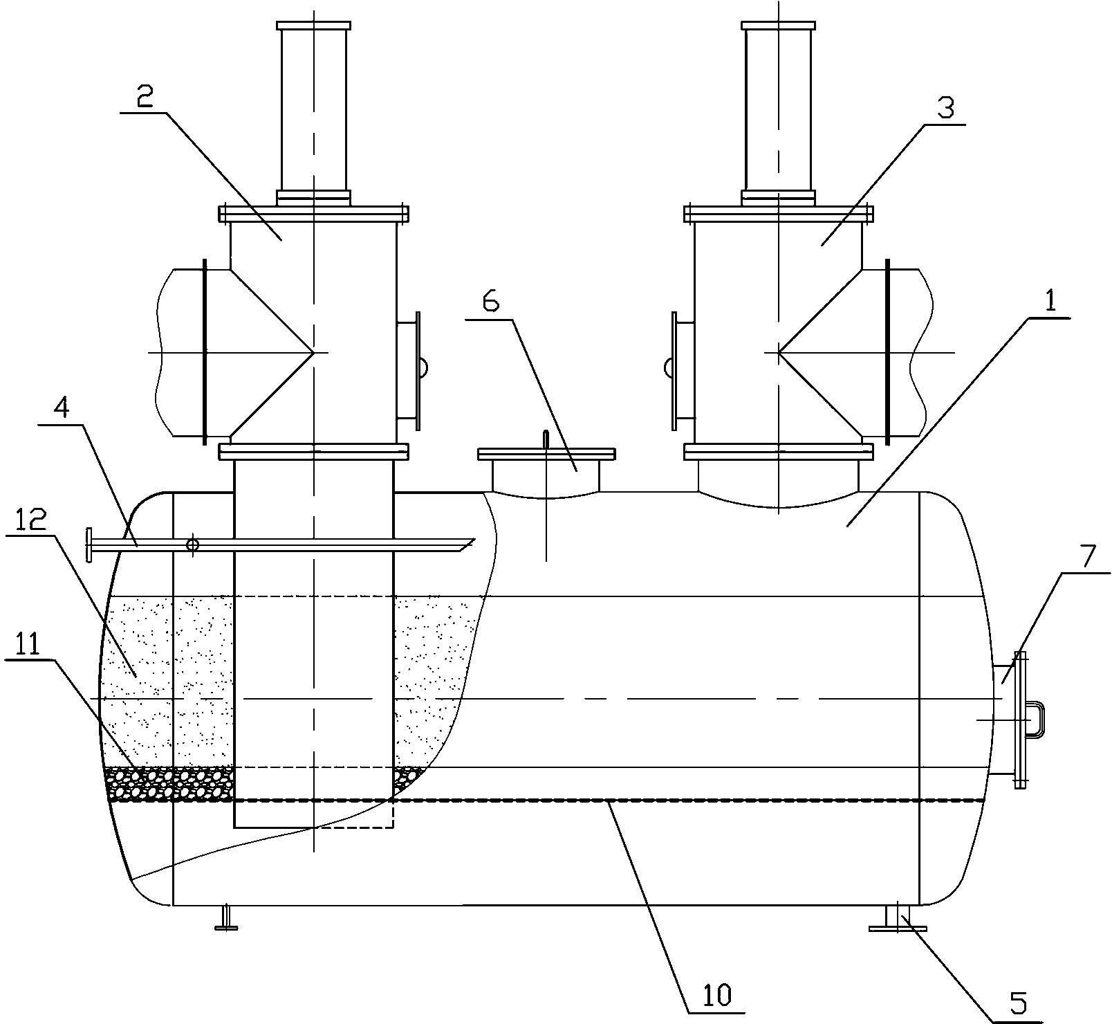
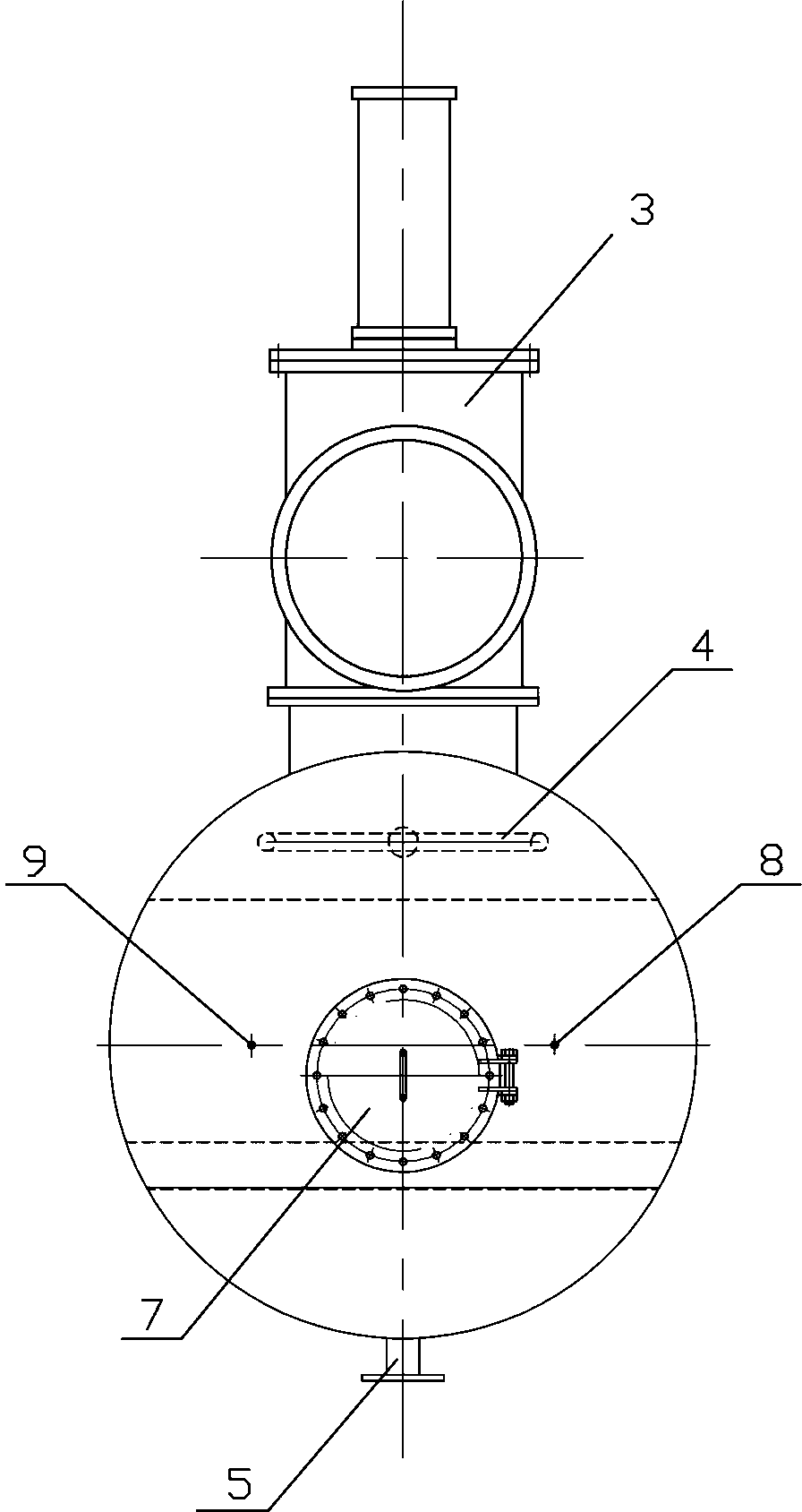
[0026] Embodiment one: refer to figure 1 , figure 2 , an organic solvent waste gas recovery and purification device, comprising an adsorption tank body 1, waste gas inlet valve 2, waste gas outlet valve 3, steam inlet pipe 4, purified gas outlet pipe 5, tank top manhole 6, tank head manhole 7. Thermometer socket 8, temperature sensor interface 9, activated carbon support plate 10, solid filler 11, and activated carbon 12. The tank body 1 of the adsorption tank is a horizontal cylinder with an elliptical head on both sides. The exhaust gas inlet valve 2 and the exhaust gas outlet valve 3 are located on the top of the tank and are close to the oval heads on both sides. The exhaust gas inlet valve 2 is connected to a pipe that passes through the tank for 10-20 cm, and the exhaust gas outlet valve 3 is connected to a pipe that passes through the tank. body 1 and pass through the activated carbon support plate 10 for about 10 to 20 cm. The steam inlet pipe 4 is located betw...
Embodiment 2
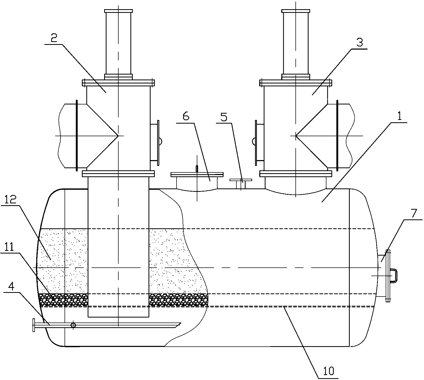
[0028] Embodiment two: refer to image 3 , an organic solvent waste gas recovery and purification device, comprising an adsorption tank body 1, waste gas inlet valve 2, waste gas outlet valve 3, steam inlet pipe 4, purified gas outlet pipe 5, tank top manhole 6, tank head manhole 7. Thermometer socket 8, temperature sensor interface 9, activated carbon support plate 10, solid filler 11, and activated carbon 12. The tank body 1 of the adsorption tank is a horizontal cylinder with an elliptical head on both sides. The exhaust gas inlet valve 2 and the exhaust gas outlet valve 3 are located on the top of the tank and close to the oval heads on both sides respectively. The connecting pipe of the exhaust gas inlet valve 2 passes through the tank 1 and passes through the activated carbon support plate 10 for about 10~20cm. The outlet valve 2 is connected with a pipeline passing through the tank body for 10-20 cm, the steam inlet pipe 4 is located between the activated carbon supp...
PUM
| Property | Measurement | Unit |
|---|---|---|
| Diameter | aaaaa | aaaaa |
Abstract
Description
Claims
Application Information
 - Generate Ideas
- Intellectual Property
- Life Sciences
- Materials
- Tech Scout
- Unparalleled Data Quality
- Higher Quality Content
- 60% Fewer Hallucinations
Browse by: Latest US Patents, China's latest patents, Technical Efficacy Thesaurus, Application Domain, Technology Topic, Popular Technical Reports.
© 2025 PatSnap. All rights reserved.Legal|Privacy policy|Modern Slavery Act Transparency Statement|Sitemap|About US| Contact US: help@patsnap.com