
Nozzle transmission mechanism for 3D printer and 3D printer with same

A 3D printer and transmission mechanism technology, applied in the field of 3D printing, can solve the problems of low positioning accuracy, unfavorable cost control, and low printing efficiency, so as to improve efficiency, reduce printing cost, and reduce defective rate. Effect

Inactive Publication Date: 2013-09-25
J H TECH ELECTRONICS GZ LTD
View PDF4 Cites 93 Cited by
  • Summary
  • Abstract
  • Description
  • Claims
  • Application Information

AI Technical Summary

Problems solved by technology

The structure of this three-axis linkage transmission mechanism is relatively complex and takes up a large space. In addition, during the printing process, when moving between different positions, three drive units are required to drive the nozzle to move in sequence. The efficiency is low, and the accuracy of positioning is not high, and the defective rate of workpieces is high; in addition, the existing three-axis linkage transmission mechanism needs to make more improvements when printing large-volume workpieces. These improvements are more complicated and not conducive to cost control

Method used


Image

  • Nozzle transmission mechanism for 3D printer and 3D printer with same
  • Nozzle transmission mechanism for 3D printer and 3D printer with same
  • Nozzle transmission mechanism for 3D printer and 3D printer with same

Examples


Embodiment Construction

[0039] Below, in conjunction with accompanying drawing and specific embodiment, the present invention is described further:

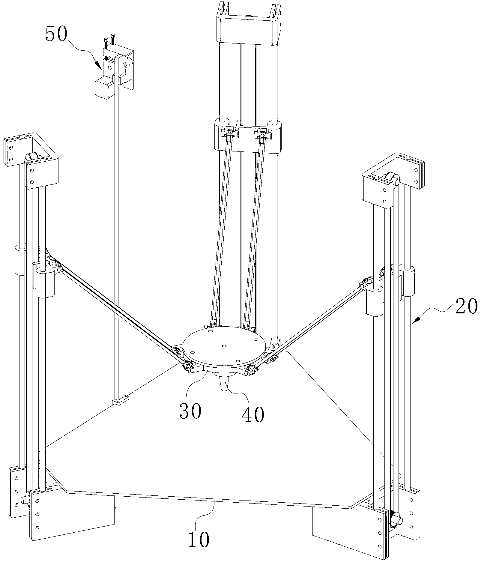
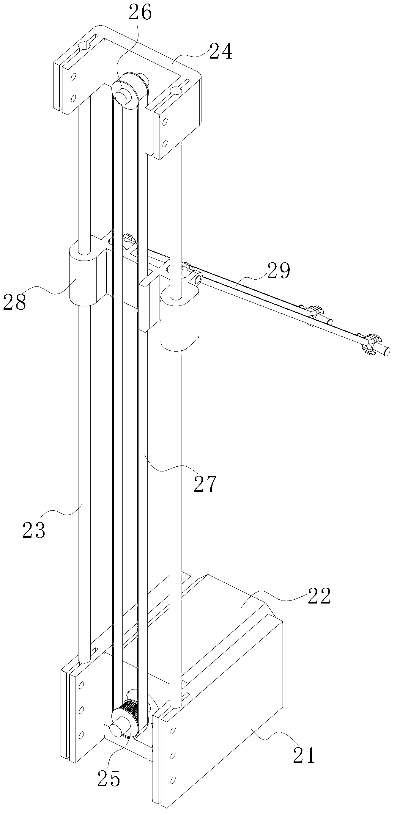
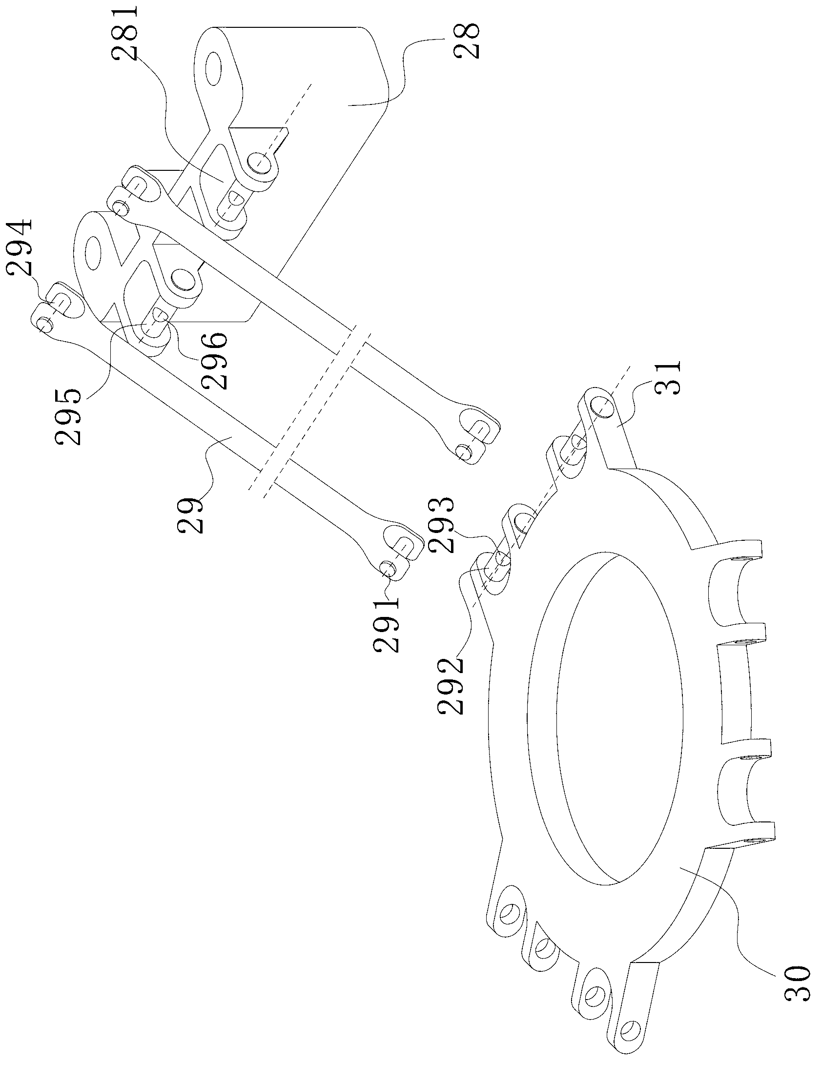
[0040] see figure 1 , 2 3. The nozzle transmission mechanism of the present invention includes a platform 10, a mounting base 30, three transmission components 20 and a controller (not shown in the figure). The platform 10 is mainly used to place the printing workpiece and serve as the installation basis of the entire transmission mechanism. The two transmission components 20 work together to drive the mounting seat 30 on which the spray head 40 is fixed to move in the height direction and the horizontal direction.

[0041] Three transmission assemblies 20 are evenly distributed on the periphery of the platform 10, and each transmission assembly 20 includes a motor base 21, a driving motor 22, two guide rods 23, a fixed seat 24, a driving pulley 25, a driven pulley 26, a synchronous Belt 27, sliding seat 28 and two connecting rods 29, wherein, motor s...


PUM


Abstract

The invention discloses a nozzle transmission mechanism for a 3D printer. The nozzle transmission mechanism comprises a platform used for holding a workpiece, a mounting seat which is positioned above the platform and is used for fixing a nozzle, more than three transmission components distributed at the periphery of the platform, and a controller used for controlling each driving motor, wherein each transmission component comprises a guide rod which extends along the height direction, a sliding seat arranged on the guide rod in a sliding mode, a driving motor used for driving the sliding seat to move up and down along the guide rod, and a connecting rod; and two ends of the connecting rod are respectively connected with the mounting seat and the sliding seat in a universal hinge mode. Three or more than three guide rods in the vertical direction are arranged only, the sliding seat on the guide rods is driven by the motor, the nozzle is driven to move in the height direction and the horizontal direction through differential motion among the sliding seat, and compared with the conventional three-axis association transmission mechanism, the nozzle transmission mechanism has the advantages of simple structure, small occupied space, high operating precision and the like, the 3D printing efficiency can be improved, and the defective percentage of the workpiece is reduced.

Description

[0001] technical field [0002] The invention relates to the technical field of 3D printing, in particular to a nozzle transmission mechanism of a 3D printer and a 3D printer having the mechanism. [0003] Background technique [0004] 3D printing technology is a rapid prototyping technology for workpieces. It is based on the digital model file of the workpiece, using materials with viscous properties after heating and softening, such as metal or plastic, to form the workpiece by layer-by-layer printing. [0005] Nozzle 3D printers are used to output consumables. During the printing process, the nozzle is required to be able to move arbitrarily on the three coordinate axes in space to deal with workpieces with different external contours. Most of the existing 3D printer nozzle transmission mechanisms use the transmission mechanism of the traditional three-axis linkage machine tool, which includes axes along the X, Y, and Z directions, and each axis is equipped with a drive ...

Claims


Application Information

Patent Timeline
IPC IPC(8): B29C67/00
Inventor 萧嘉鑫李一奇
Owner J H TECH ELECTRONICS GZ LTD
Learn More