Urea pump for treating tail gas of diesel engine
A diesel engine and exhaust gas treatment technology, applied in the field of urea pumps, can solve the problems of failing to meet exhaust gas treatment emission standards and affecting the development of the diesel automobile industry, and achieve the effects of simple structure, low cost, and flexible flow control
- Summary
- Abstract
- Description
- Claims
- Application Information
AI Technical Summary
Problems solved by technology
Method used
Image
Examples
Embodiment Construction
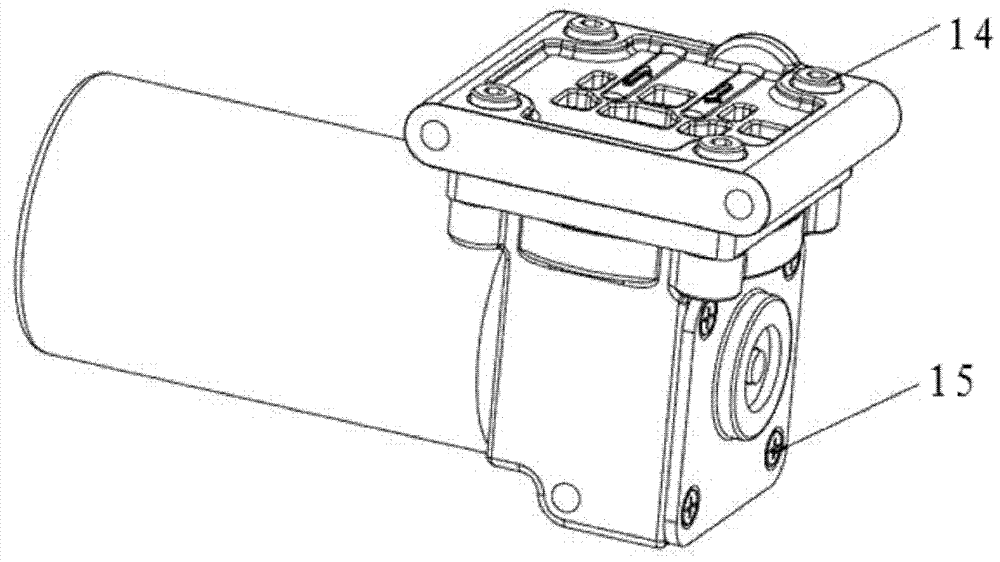
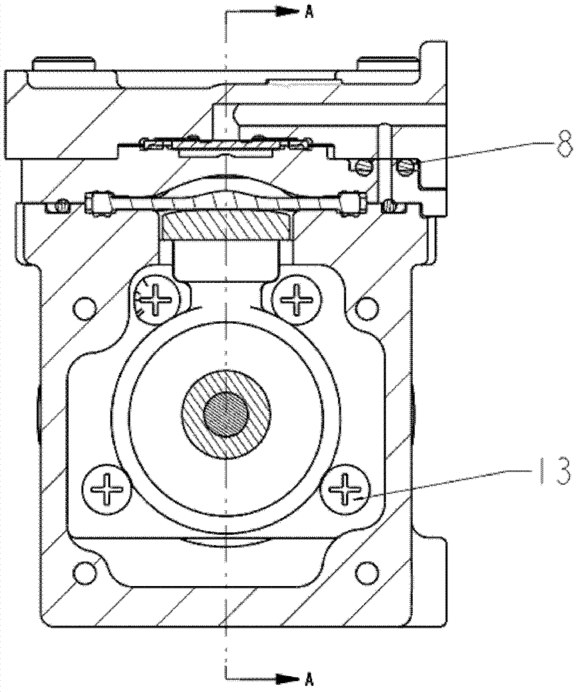
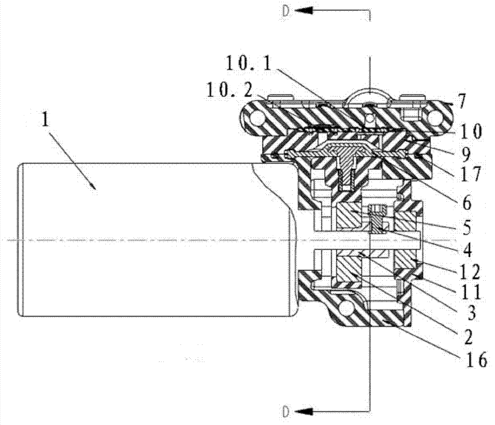
[0017] combine Figure 1-3 , is a structural schematic diagram of a diesel engine exhaust gas treatment urea pump. The diesel engine exhaust gas treatment system urea pump includes an engine control module ECM (Engine Control Module), which is electrically connected to a motor controller through a PWM signal control line, and the motor controller is connected to the motor controller. The urea pump is electrically connected; the flow of the urea pump is controlled by using the PWM (pulse width modulation) signal of the automobile engine ECM to control the motor speed through the motor controller.
[0018] In the figure, the motor 1 drives the eccentric wheel 3 and the connecting rod bearing 5 installed on the eccentric wheel 3 through the output shaft of the motor to run. The rod 2 drives the diaphragm 6 mounted on the connecting rod 2 to reciprocate up and down in the arc-shaped cavity between the upper end surface of the pump body 16 and the valve seat 9 on it. When the conne...
PUM
 Abstract
Description
Claims
Application Information
 - R&D
- Intellectual Property
- Life Sciences
- Materials
- Tech Scout
- Unparalleled Data Quality
- Higher Quality Content
- 60% Fewer Hallucinations
Browse by: Latest US Patents, China's latest patents, Technical Efficacy Thesaurus, Application Domain, Technology Topic, Popular Technical Reports.
© 2025 PatSnap. All rights reserved.Legal|Privacy policy|Modern Slavery Act Transparency Statement|Sitemap|About US| Contact US: help@patsnap.com


