
Vertical combustion gas turbine

A gas turbine, gas turbine technology, applied in gas turbine devices, mechanical equipment, engine components, etc., can solve the problems of reducing aerodynamic efficiency, low pressure ratio, large gas flow loss, etc., to improve aerodynamic efficiency, improve mechanical efficiency, reduce shaft effect on frictional losses

Active Publication Date: 2013-09-25
BEIJING INSTITUTE OF TECHNOLOGYGY
View PDF6 Cites 11 Cited by
  • Summary
  • Abstract
  • Description
  • Claims
  • Application Information

AI Technical Summary

Problems solved by technology

The radial flow turbine has radial air intake and axial air outlet, also known as centripetal type; the compressor adopts axial air intake and radial air outlet, which is called centrifugal type, which makes the gas inlet flow angle and The outlet airflow angle is arranged at 90°, the gas flow loss is large, and the aerodynamic efficiency is reduced; the existing axial inlet and radial outlet structure will have a lower pressure ratio than the radial flow compressor with radial inlet and radial outlet

Method used


Image

  • Vertical combustion gas turbine
  • Vertical combustion gas turbine
  • Vertical combustion gas turbine

Examples


Embodiment Construction

[0029] In order to illustrate the technical solutions of the present invention more clearly, the present invention will be further described in detail below with reference to the accompanying drawings and specific embodiments.

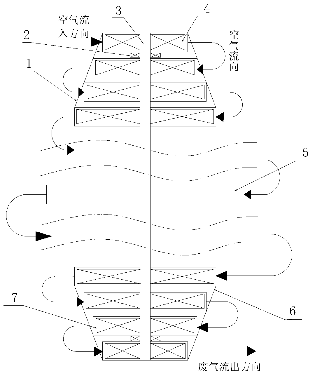
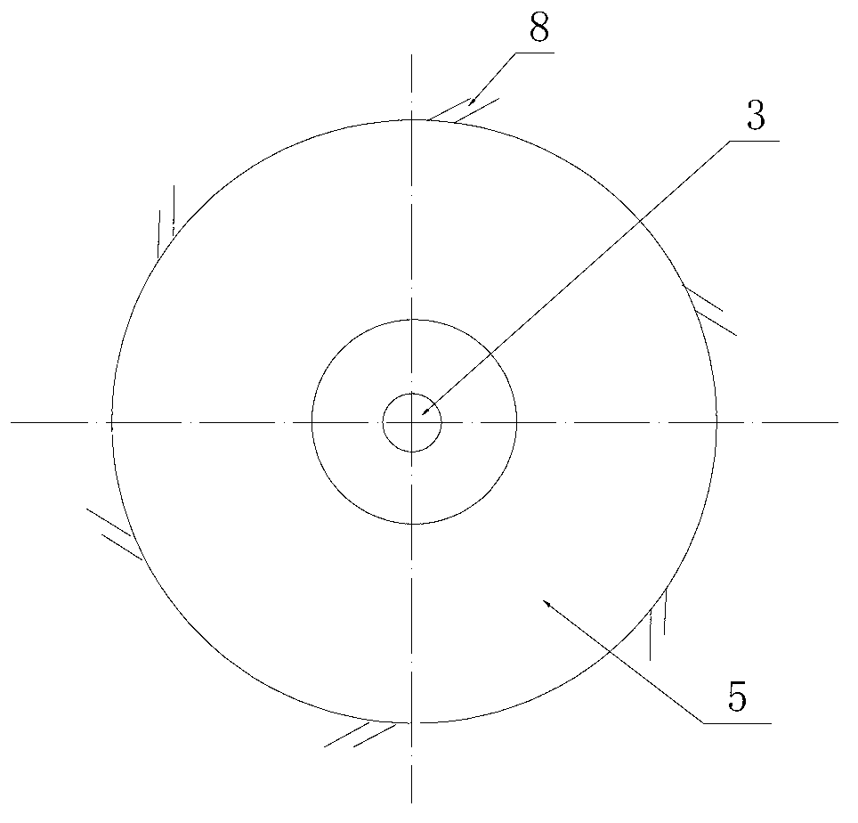
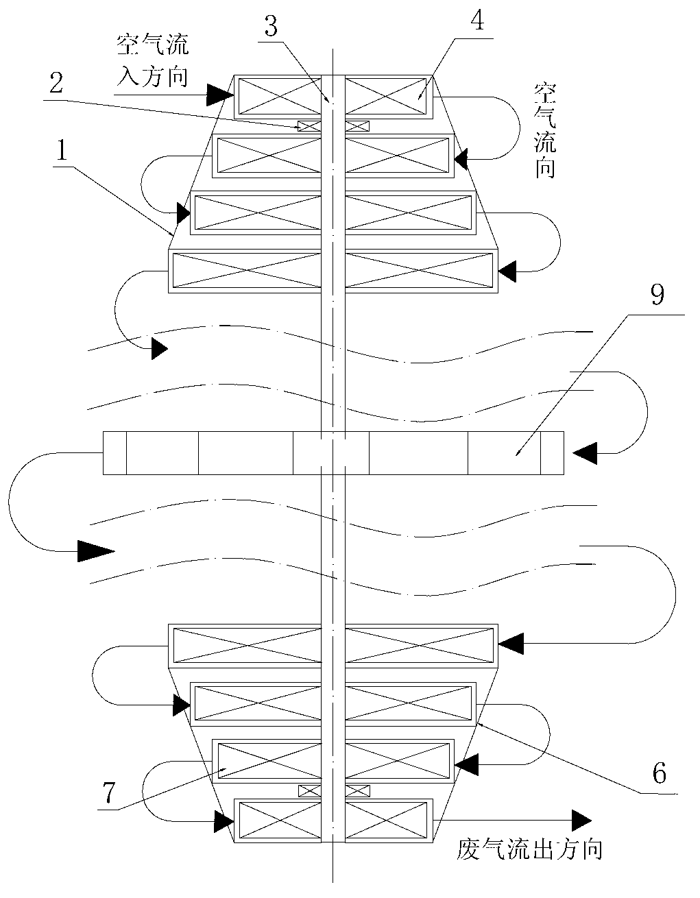
[0030] The vertical gas turbine of the present invention includes a gas turbine casing, a compressor 1, a combustion chamber, a gas turbine 6, a rotating shaft 3, and a non-liquid oil-lubricated bearing 2 located inside the gas turbine casing. The rotating shaft 3 is arranged perpendicular to the ground, The compressor 1 and the gas turbine 6 are respectively installed on both ends of the rotating shaft 3 through the non-liquid oil lubricated bearings 2. The combustion chamber is located between the compressor 1 and the gas turbine 6. The air port and the air outlet are radial air inlet and radial air outlet. In order to match the structure of radial intake and radial exhaust of the gas turbine, the combustion chamber adopts two new structures, namely ...


PUM


Abstract

The invention provides a vertical combustion gas turbine. The vertical combustion gas turbine comprises a combustion gas turbine shell, and a gas compressor, a combustion chamber, a gas turbine, a rotary shaft and non-liquid oil lubricating bearings which are located inside the combustion gas turbine shell, wherein the rotary shaft is arranged in a manner of being vertical to the ground; the pressure machine and the gas turbine are respectively mounted at the two ends of the rotary shaft through the non-liquid oil lubricating bearings; the combustion chamber is located between the gas compressor and the gas turbine; air inlets and air outlets of the gas compressor and the gas turbine are radial air inlets and radial air outlets. According to the vertical combustion gas turbine disclosed by the invention, the vertical installation of an impeller mechanical rotor is realized; the rotor dynamic performance of an impeller machine is improved, the service life of the impeller machine is prolonged, and the reliability of the impeller machine is improved; a flowing medium flows through all parts in a manner of radial air feeding and radial air discharging, so as to reduce the gas flowing swerving loss, realize a high pressure ratio and improve the pneumatic efficiency; an axial pneumatic load is not generated and the axial friction loss is relieved; the mechanical efficiency is improved; the non-liquid oil lubricating bearings are adopted so that the structure is simplified and the axial length of the impeller machine is shortened.

Description

technical field [0001] The invention relates to an impeller machine, in particular to a vertical gas turbine with a rotating shaft arranged upright. Background technique [0002] Turbomachinery is a kind of machine that takes continuous rotating blades as the main body to convert energy between fluid working medium and shaft power. It can be a prime mover or a working machine. The working process of the turbomachinery is a process in which the energy of the fluid or process material (such as powder, particles) and the mechanical energy are converted into each other or the energy transfer between the fluids of different energy. Because in almost all fields of technology and life, it is necessary to perform energy conversion by means of fluids or process materials or to transport fluid media or process materials, so the turbomachinery is a kind of mechanical equipment with a wide range of applications. With the continuous emergence of new technologies, new processes and new m...

Claims


Application Information

Patent Timeline
IPC IPC(8): F02C3/00F02C7/06F01D5/00
Inventor 黄若姜雅力段晓丽张威力
Owner BEIJING INSTITUTE OF TECHNOLOGYGY
Learn More