Y-shaped double-side-roller push and pull chain

A technology of pushing zippers and rollers, applied in the directions of belts/chains/gears, chain elements, transmission chains, etc., can solve the problems of easy damage to the screw nut, service life, application obstacles in compact space, and inability to meet cost performance, and achieve assembly adjustment. Convenience, compact structure, convenient assembly and disassembly and replacement

Active Publication Date: 2013-09-25
SHANGHAI SONCO QUICK CHANGE SYST
View PDF6 Cites 4 Cited by
  • Summary
  • Abstract
  • Description
  • Claims
  • Application Information

AI Technical Summary

Problems solved by technology

This kind of structure is limited in space when realizing the vertical and horizontal push-pull function. At the same time, when the long-distance push-pull function is realized, the stability is poor, it is easy to shake, and the crawling causes shutdown. The screw nut is easily damaged and affects the service life of the system. The structural space of the chain drive meets the requirements, and at the same time avoids the disadvantages of shaking and cra

Method used


Image

  • Y-shaped double-side-roller push and pull chain
  • Y-shaped double-side-roller push and pull chain
  • Y-shaped double-side-roller push and pull chain

Examples


Embodiment 1

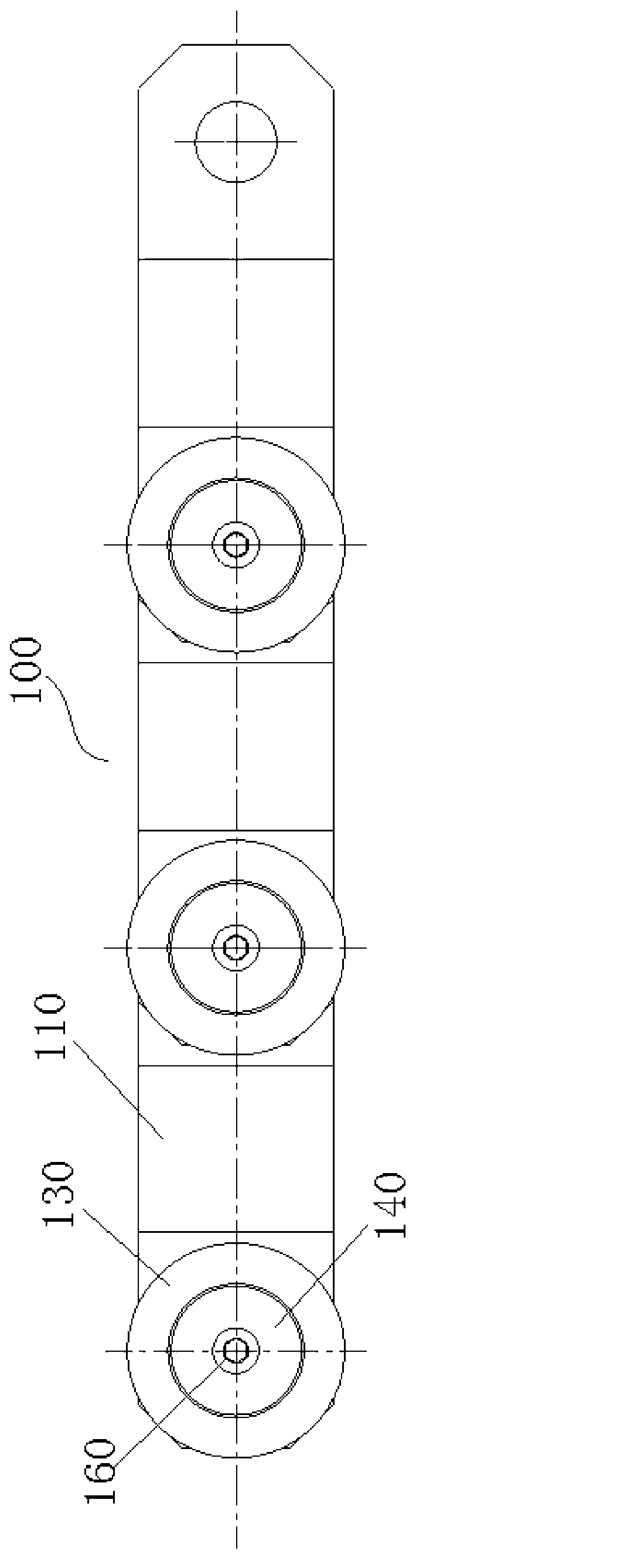
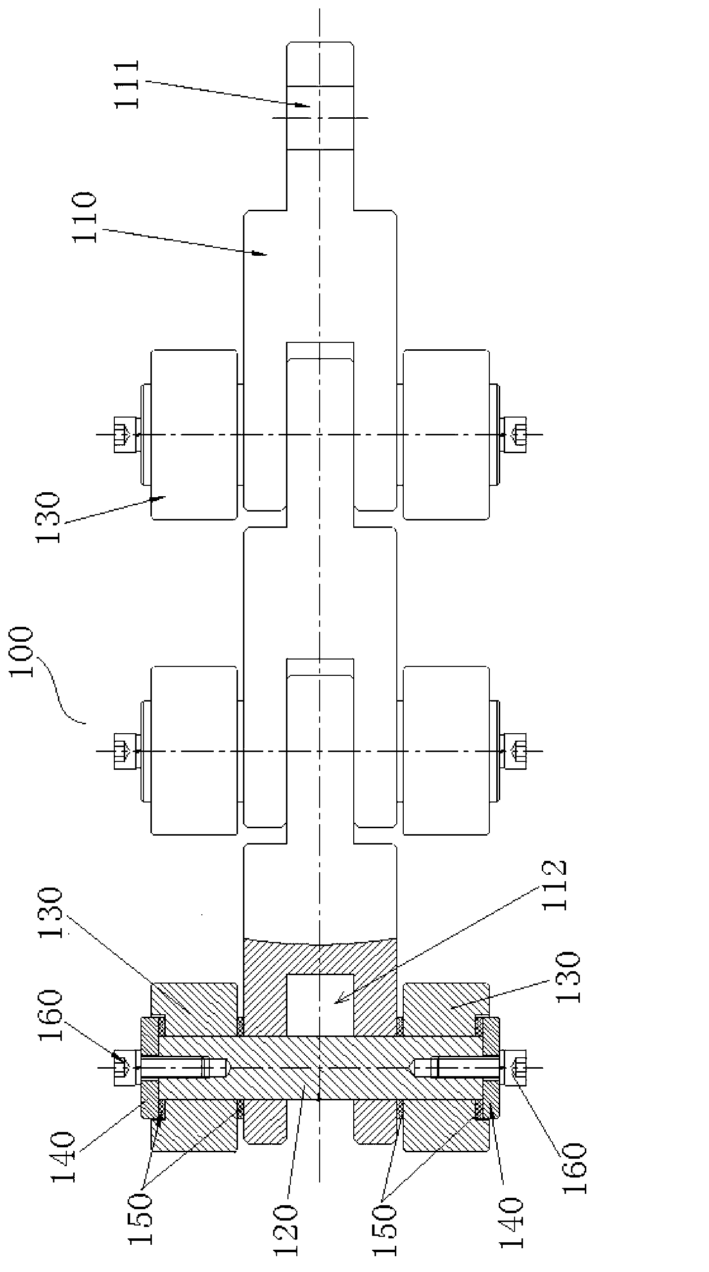
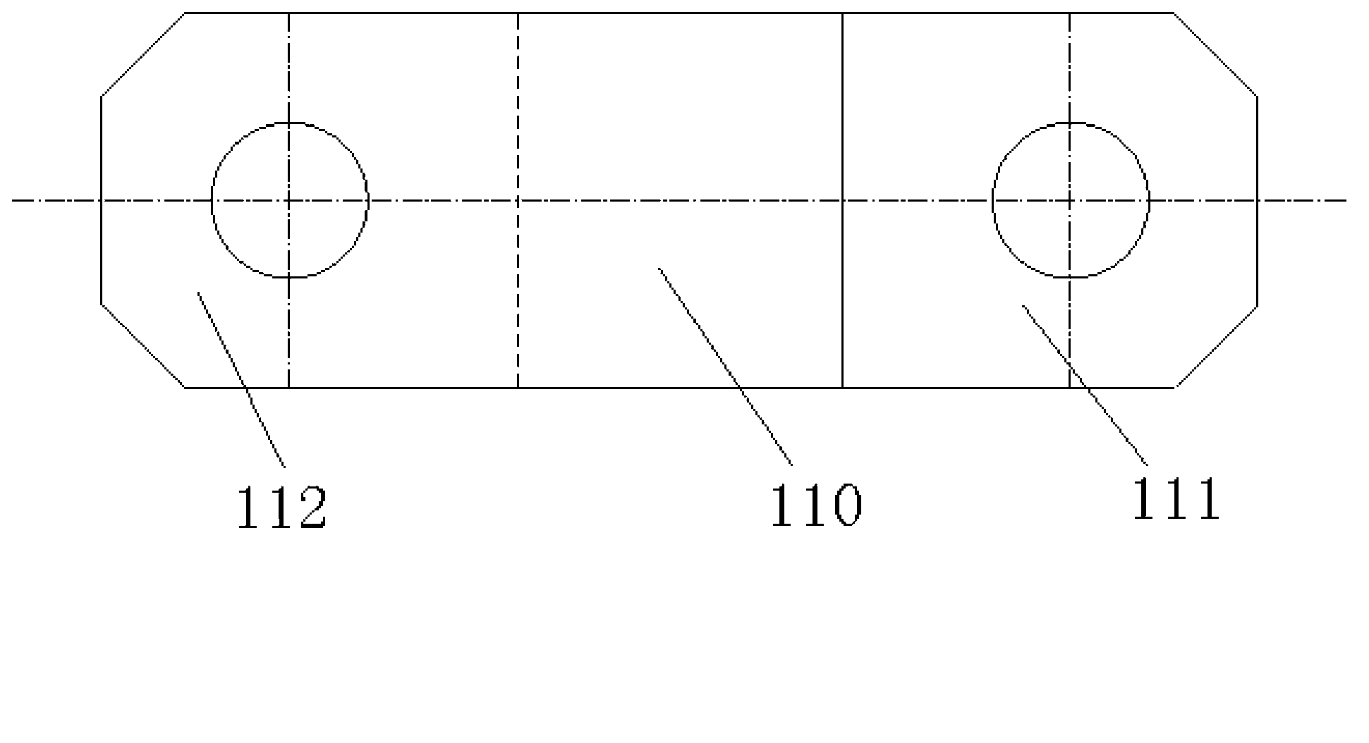
[0032] figure 1 The front view of the Y-shaped double-sided roller push zipper strip of Example 1, figure 2 It is a top view of the Y-shaped double-sided roller push fastener chain of Example 1. Such as figure 1 with figure 2 As shown, the Y-shaped double-sided roller push zipper strip 100 proposed in this embodiment includes several image 3 with Figure 4 In the Y-shaped structure of the chain link 110 shown, one end of the chain link 110 is a convex end 111 and the other end is a concave end 112. The adjacent chain links 110 are connected in series by the convex end 111 and the concave end 112 to form a whole. Such as figure 2 As shown, the male end 111 is inserted into the female end 112, and a center pin 120 is inserted through each of the male and female ends 111 and 112 that engage with each other for connection and fixation. The center pin 120 protrudes from two of the chain links 110. Each end is provided with a roller 130 for guiding and motion support.

[0033] Such...

Embodiment 2

[0038] Figure 7 It is a top view of the Y-shaped double-sided roller push fastener chain of the second embodiment. Such as Figure 7 As shown, the second embodiment is similar to the first embodiment above in structure, except that the roller 130 is a combined bearing structure, and the combined bearing structure includes a needle roller bearing 131 and a bearing roller 132, and the needle roller bearing 131 is sleeved on The center pin 120 protrudes from the end of the chain link 110, and the bearing roller 132 is sleeved on the needle bearing 131, which can realize operation with lower friction resistance, smoother work, and higher running speed. Exemplary, such as Figure 7 As shown, a baffle 140 for fixing the combined bearing structure is provided on each end surface of the center pin 120. The baffle 140 is fixed on the end surface of the center pin 120 by a screw 160. The screws 160 sequentially press the baffle and the outer side. End bearing, combined bearing struct...


PUM


Abstract

The invention discloses a Y-shaped double-side-roller push and pull chain comprising a plurality of Y-shaped chain links. One end of each chain link is a projecting end, and the other end of the chain link is a socket end. The adjacent chain links are integrally connected in sequence and in series by mutual meshing of the projecting ends and the socket ends, the projecting ends are inserted into the socket ends, a central pin penetrates each two mutually meshed projecting and socket ends to fixedly connect the ends, and a roller for guidance and motion support is disposed at each end of the central pin, extending out of the chain link. The Y-shaped double-side-roller push and pull chain can transmit both pulling force and pushing force just under the restraint condition, meets the requirement of push and pull application, and has the advantages that the structure is simple, production is easy, assembly and adjustment are facilitated, the chain is simple to use and maintain, compact in structure, high in intensity and high in bearing capacity, the application requirement of heavy load in limited space can be met and the chain is applicable to different types of rollers for low-friction operation, effectively energy-saving and long in service life.

Description

Technical field [0001] The present invention relates to the technical field of mechanical transmission, in particular to a Y-shaped double-sided roller push zipper strip that can transmit both pulling force and thrust. Background technique [0002] In stamping production, especially in the hemming stamping process, due to changes in production mode, mass production gradually transitions to a multi-variety, small-batch production mode. In order to improve production efficiency and reduce equipment and site investment, limited space is required It realizes the vertical and horizontal push-pull exchange function of multiple sets of molds. [0003] The current mold push-pull exchange device mainly adopts a screw drive structure. This structure is subject to certain restrictions in space when realizing the vertical and horizontal push-pull function. At the same time, when the long-distance push-pull function is realized, the stability is poor, and it is prone to jitter, crawling and ca...

Claims


Application Information

Patent Timeline
IPC IPC(8): F16G13/20F16G13/06F16G15/00
Inventor 胡三华王俊廖腊财
Owner SHANGHAI SONCO QUICK CHANGE SYST
Why Eureka
Try Eureka