Heat-pump water heater cold shielding system for protecting compressor

A heat pump water heater and compressor technology, applied in compressors, fluid heaters, refrigerators, etc., can solve the problems of damage to the compressor, less evaporation, and insufficient suction of the compressor, so as to reduce the fluctuation of liquid supply and improve the Heat exchange efficiency, the effect of increasing the heat exchange area

Inactive Publication Date: 2013-09-25
ZHEJIANG AMA & HIEN TECH
View PDF7 Cites 6 Cited by
  • Summary
  • Abstract
  • Description
  • Claims
  • Application Information

AI Technical Summary

Problems solved by technology

Although the heat pump water heater can make the flow of refrigerant in the heat pump cycle system relatively stable by controlling the "two-position three-way" refrigeration solenoid valve in winter or summer, the heat pump water heater can only adjust the extreme conditions of winter and summer, and cannot Real-time control of refrigerant flow throughout the system
When the two capillary tubes are suddenly connected, it is easy to cause insufficient evaporation of the refrigerant flowing through the evaporator, causing part of the liquid refrigerant to enter the compressor, which will cause liquid shock to the compressor and damage the compressor; When one of the capillary tubes is damaged, the amount of refrigerant in the evaporator will suddenly decrease, resulting in too little evaporation, insufficient suction of the compressor, and even the compressor cannot work normally. Therefore, this energy-saving heat pump water heater still cannot Fundamentally solve the problem of the compressor being damaged by liquid shock and insufficient suction

Method used


Image

  • Heat-pump water heater cold shielding system for protecting compressor

Examples


Embodiment Construction

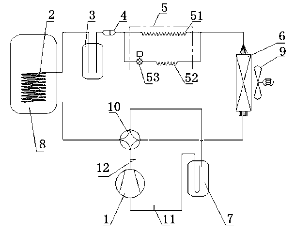
[0029] see figure 1 , a heat pump water heater cooling shield system for protecting compressors, including a compressor 1, a condenser 2, a throttling device 5, an evaporator 6, and a gas-liquid separator 7 connected in sequence to form a circulation loop; the throttling device 5 It includes a main capillary 51 and an auxiliary capillary 52 arranged in parallel, and the liquid inlet end of the auxiliary capillary 52 is provided with a real-time flow control device. The real-time flow control device includes a solenoid valve 53, a controller electrically connected to the solenoid valve 53, and a temperature sensor electrically connected to the controller. The refrigerant flow rate of the solenoid valve 53. The controller has a PWM switch, and after receiving the internal and external temperature feedback of the system, the controller controls the flow of refrigerant flowing through the solenoid valve 53 in real time through the output of the PWM switch.

[0030] This embodime...


PUM


Abstract

The invention discloses a heat-pump water heater cold shielding system for protecting a compressor. The heat-pump water heater cold shielding system comprises the compressor, a condenser, a throttling device, an evaporator and a gas-liquid separator which are sequentially connected to form a circulation loop, the throttling device comprises a primary capillary tube and a secondary capillary tube which are parallelly connected, and a real-time flow control device is arranged at a liquid inlet end of the secondary capillary tube. Since the real-time flow control device is arranged at the liquid inlet end of the secondary capillary tube, refrigerant flow passing through the secondary capillary tube is adjusted in real time, appropriate amount of refrigerant flows into the evaporator to be evaporated sufficiently, gaseous refrigerant returned into the compressor is guaranteed not to be mixed with liquid, and influence on service life of the compressor from liquid impact is eliminated to the greatest extent. In addition, since the appropriate amount of the refrigerant participates into evaporation in the evaporator, the gaseous refrigerant returned into the compressor is guaranteed to be sufficient, system efficiency is prevented from being affected by the compressor due to insufficient refrigerant, and even affect on normal work of the compressor is avoided.

Description

technical field [0001] The invention relates to the field of heat pump water heaters, in particular to a heat pump water heater cold shield system for protecting a compressor. Background technique [0002] Among the main components of the heat pump water heater, the important role of the compressor is self-evident, and the service life of the compressor will directly determine the service life of the heat pump water heater. The throttling device in a traditional heat pump water heater is a capillary tube with a certain length. With the seasonal change of the outside temperature, the pressure difference between the two ends of the capillary tube will also change greatly, which will lead to the refrigerant entering the evaporator. Too much or too little. If the amount of refrigerant is too much, the refrigerant will not evaporate sufficiently in the evaporator, some liquid refrigerant will enter the compressor, and the liquid refrigerant will cause liquid shock to the compres...

Claims


Application Information

Patent Timeline
Patent Type & Authority Applications(China)
IPC IPC(8): F24H4/04F25B41/06F25B49/02F25B31/00F28F19/00F28F1/40F25B41/37
CPCY02B30/70
Inventor 黄道德
Owner ZHEJIANG AMA & HIEN TECH
Why Eureka
Try Eureka