Charge-discharge equalization control circuit of battery pack
A charge-discharge circuit and equalization control technology, which is applied in the direction of battery circuit devices, circuit devices, collectors, etc., can solve the problem of not being able to effectively maintain the physical and chemical properties of lithium iron phosphate batteries, shortening the life of battery packs, and low specific capacity, etc. question
- Summary
- Abstract
- Description
- Claims
- Application Information
AI Technical Summary
Problems solved by technology
Method used
Image
Examples
Embodiment 1
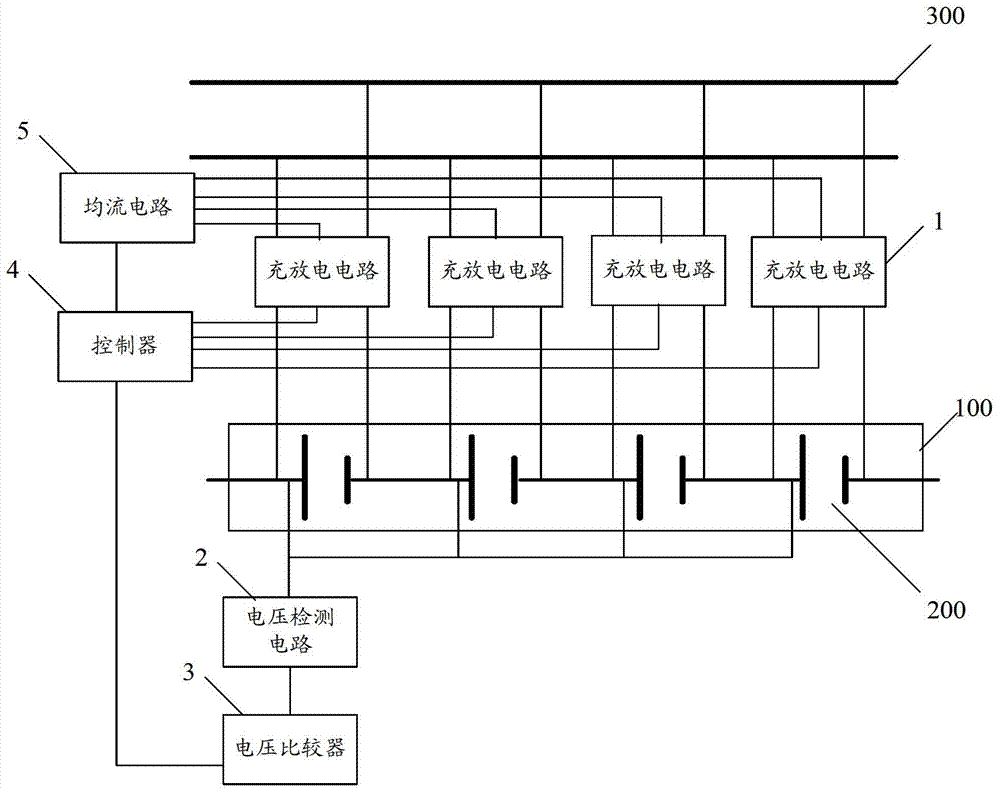
[0049] figure 1 It is a schematic structural diagram of a charge-discharge balance control circuit for a battery pack provided in an embodiment of the present application.
[0050] The control circuit is used to control the charging process of the battery pack, so that the battery cells in the battery pack can achieve balanced charging, and for the battery pack, at least two battery cells are included. figure 1 Among them, 100 is a battery pack, 200 is a battery cell, and 300 is a power cord for charging the battery pack.
[0051] Such as figure 1 As shown, the control circuit includes: a charging and discharging circuit 1, a voltage detection circuit 2, a voltage comparator 3, a controller 4, a current equalizing circuit 5 and a discharge switch (not shown in the figure).
[0052] The input terminal of the charging and discharging circuit 1 is connected to the power line 300, and the output terminals of the charging and discharging circuit 1 are respectively connected to at...
Embodiment 2
[0084] In order to avoid energy loss caused by frequent detection of the battery cell voltage, in other embodiments of the present application, the interval time of detection can also be set during the charging process of different modes.
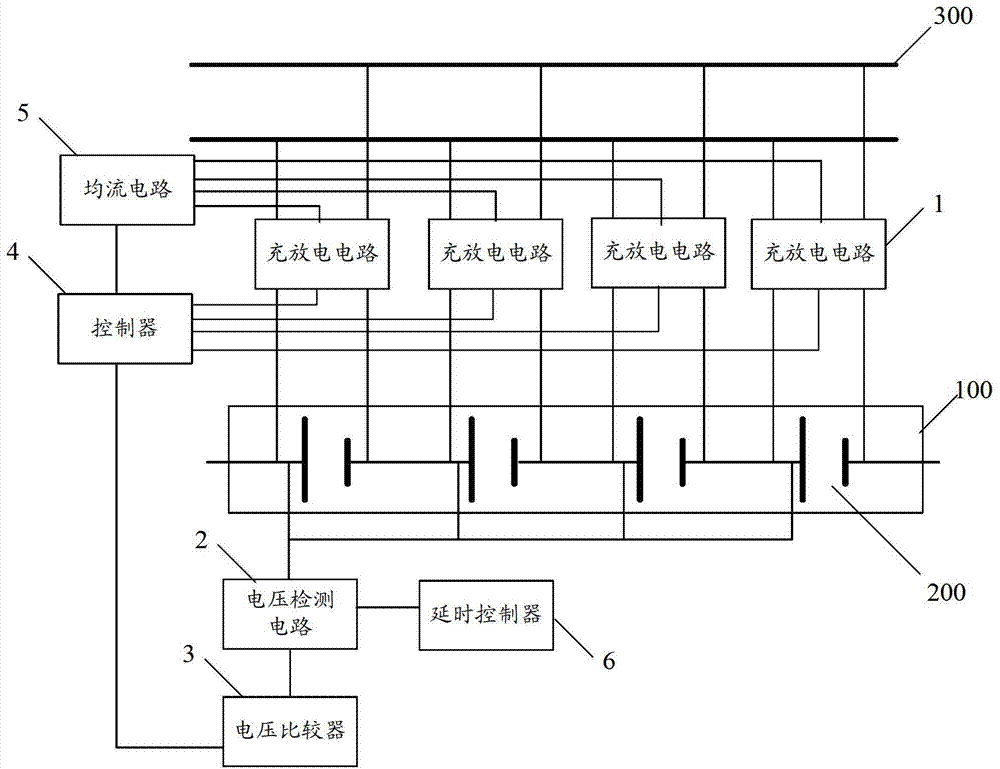
[0085] Figure 5 A schematic structural diagram of another charging and discharging equalization control circuit for a battery pack provided in an embodiment of the present application.
[0086] Such as Figure 5 As shown, the charge-discharge equalization control circuit may further include: a delay controller 6, and the delay controller 4 is connected to the voltage detection circuit 2 for controlling the detection interval of the voltage detection circuit.
[0087] When the average voltage is less than the first preset voltage threshold and the charging current is between 0.1C and 0.2C, a first delay instruction is generated and sent to the voltage detection circuit to control the voltage detection circuit 2 to delay the first preset A...
Embodiment 3
[0093] In the first embodiment above, it is possible to adjust the charging condition of the battery cell with a faster charging speed, but after the adjustment is completed, the charging condition of the battery cell will tend to be normal. , will again cause this cell to charge slower than the other cells.
[0094] For this reason, in the embodiment of this application, such as Figure 6 As shown, the controller 4 in the control circuit may also include: a third comparator 49 and a third flip-flop 50, wherein:
[0095] The third comparator 49 is connected with the voltage comparator 3, and is used for judging whether the voltage difference of the battery cells in the battery pack is less than a preset threshold, where the preset threshold takes into account the difference between the cells The difference is set, that is, the small difference between the battery cells is allowed;
[0096] The third flip-flop 50 is connected with the third comparator 49, and is used to gener...
PUM
 Abstract
Description
Claims
Application Information
 - R&D
- Intellectual Property
- Life Sciences
- Materials
- Tech Scout
- Unparalleled Data Quality
- Higher Quality Content
- 60% Fewer Hallucinations
Browse by: Latest US Patents, China's latest patents, Technical Efficacy Thesaurus, Application Domain, Technology Topic, Popular Technical Reports.
© 2025 PatSnap. All rights reserved.Legal|Privacy policy|Modern Slavery Act Transparency Statement|Sitemap|About US| Contact US: help@patsnap.com


