Interleaved spin-locking imaging

A lock-on-pulse, image-representation technique for use in the field of spin-lattice relaxation pulse sequences, which can solve the problems of patient discomfort during scan times, increase motion artifacts, sacrifice scan resolution or anatomical coverage, and achieve short repetition times , the effect of reducing the scan time

Inactive Publication Date: 2013-09-25
KONINKLJIJKE PHILIPS NV
View PDF6 Cites 4 Cited by
  • Summary
  • Abstract
  • Description
  • Claims
  • Application Information

AI Technical Summary

Problems solved by technology

Longer scan times are not only uncomfortable for the patient, but also increase the chance of motion artifacts
Scan resolution or anatomical coverage is often sacrificed to reduce scan time

Method used


Image

  • Interleaved spin-locking imaging
  • Interleaved spin-locking imaging
  • Interleaved spin-locking imaging

Examples


Embodiment Construction

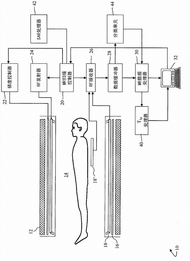
[0018] refer to figure 1 , the magnetic resonance imaging system 10 includes a main magnet 12 that generates a temporally uniform B across the examination region 14 0 field. The main magnet can be a ring or bore magnet, a C-shaped open magnet, open magnets of other designs, and the like. The gradient magnetic field coil 16 disposed adjacent to the main magnet acts to move along with respect to B 0 Selected axis of the magnetic field to generate a magnetic field gradient. A radio frequency coil, such as a whole body radio frequency coil 18, is positioned adjacent to the examination region. Optionally, in addition to or instead of the whole body RF coil 18, a local or surface RF coil 18' is provided.

[0019] A scan controller 20 controls a gradient controller 22 which causes the gradient coils to apply selected phase-encoding gradients across the imaging region, as may be appropriate for a selected magnetic resonance imaging or spectroscopy sequence. The scan controller 20...


PUM


Abstract

A magnetic resonance (MR) system 10 includes a scan controller 20 which generates a plurality of like MR pulse sequences TR. Each pulse sequence includes a plurality (m) of RF excitation pulses EXC which selectively excite a nuclear species, a plurality of different spin lock pulses SL1, SL2, SLm before each RF excitation pulse EXC, a plurality of data readout intervals RE1, RE2,..., REm. A SAR unit 42 determines a SAR value corresponding to the pulse sequence and determines a shortest repetition time for the pulse sequence based on the SAR value. A plurality of pulse sequences TR are applied, each corresponds to a single phase encode. The pulse sequences are identical except for the phase encode gradients such that a plurality of T1[rho]-weighted images of the examination region are generated. A T1[rho] processor 40 analyzes the T1[rho]-weighted images and generates a T1[rho] map of the examination region according to the analysis.

Description

technical field [0001] This application relates to the field of magnetic resonance. It finds particular application in spin-lattice relaxation pulse sequences for magnetic resonance imaging and magnetic resonance spectroscopy. Background technique [0002] Magnetic resonance imaging (MRI) and magnetic resonance spectroscopy (MRS) systems are commonly used in the examination and management of patients. With this system, the nuclear spins of the body tissue to be examined are controlled by a static main magnetic field B 0 aligned, and subjected to a transverse magnetic field B oscillating in the radio frequency band 1 excitation. In imaging, the relaxation signal is exposed to a gradient magnetic field to localize the resulting resonance. The relaxation signal is received to form a single or multi-dimensional image in known manner. In spectroscopy, information about tissue composition is carried in the frequency content of the resonance signal. [0003] MR tissue contras...

Claims


Application Information

Patent Timeline
Patent Type & Authority Applications(China)
IPC IPC(8): G01R33/44
CPCG01R33/288G01R33/448G01R33/32
Inventor E·B·韦尔奇
Owner KONINKLJIJKE PHILIPS NV
Why Eureka
Try Eureka