A rubber grinding machine for rubber rollers

A grinding machine and rubber roller technology, which is applied in the direction of cutting tools for lathes, turning equipment, metal processing machinery parts, etc., can solve the problem of destroying the dynamic balance of the steel core, the rigidity of the steel core, the destruction of the dynamic balance of the metal rod, and dust pollution in the operating place, etc. problems, to improve the processing technology, reduce the waste of energy and raw materials, and facilitate the effect of brushing and drying

Active Publication Date: 2016-05-25
JINAN POWER RUBBER ROLLER EQUIP
View PDF7 Cites 3 Cited by
  • Summary
  • Abstract
  • Description
  • Claims
  • Application Information

AI Technical Summary

Problems solved by technology

[0003] The traditional steel core surface treatment process is sandblasting and surface threading. The former process has disadvantages such as high labor intensity, high cost, and dust pollution in the operating place. The latter process will destroy the dynamic balance and steel core of the original steel core. Rigidity and other disadvantages
[0004] Simultaneously the processing technology that adopts at present also has complex and loaded down with trivial details technology, time-consuming and laborious, problems such as low production efficiency: (1) utilize lathe to carry out turning to rubber roller; (2) utilize gasoline or toluene to clean; (3) dry, when encountering Ovens are often used to heat in cold weather, humid air and deadlines; (4) apply adhesive; (5) encapsulation
At the same time, during turning, if the workpiece clamping axis cannot be completely concentric with the lathe chuck, metal layers of different thicknesses will be turned off along the surface of the workpiece, thereby destroying the dynamic balance of the metal rod and causing the workpiece to be scrapped

Method used


Image

  • A rubber grinding machine for rubber rollers
  • A rubber grinding machine for rubber rollers
  • A rubber grinding machine for rubber rollers

Examples


Embodiment Construction

[0031] The present invention will be further described below in conjunction with the accompanying drawings and embodiments.

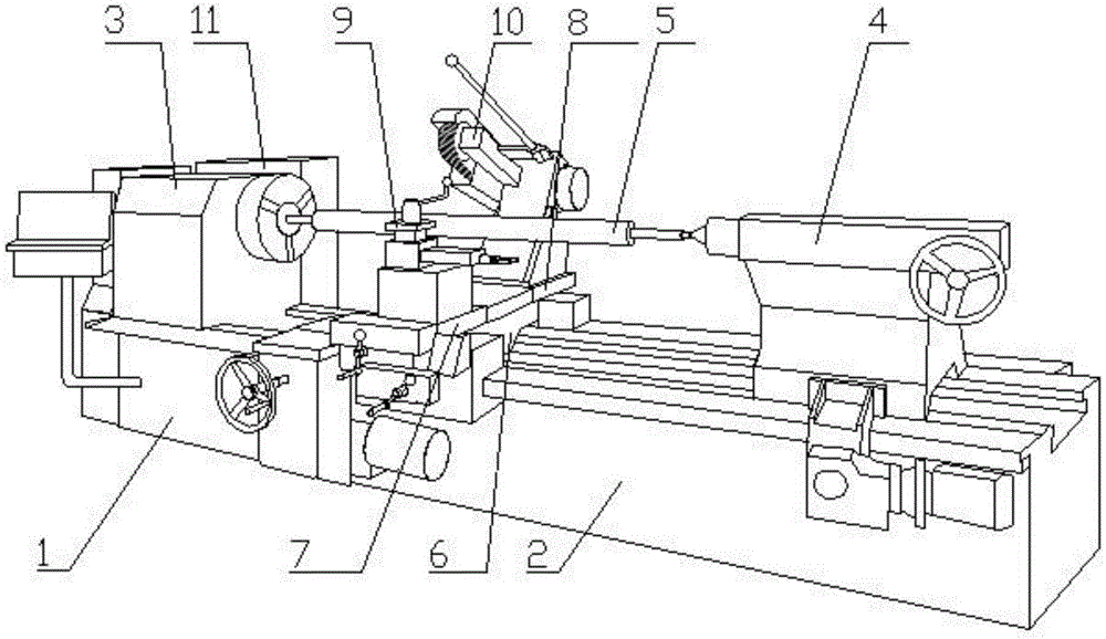
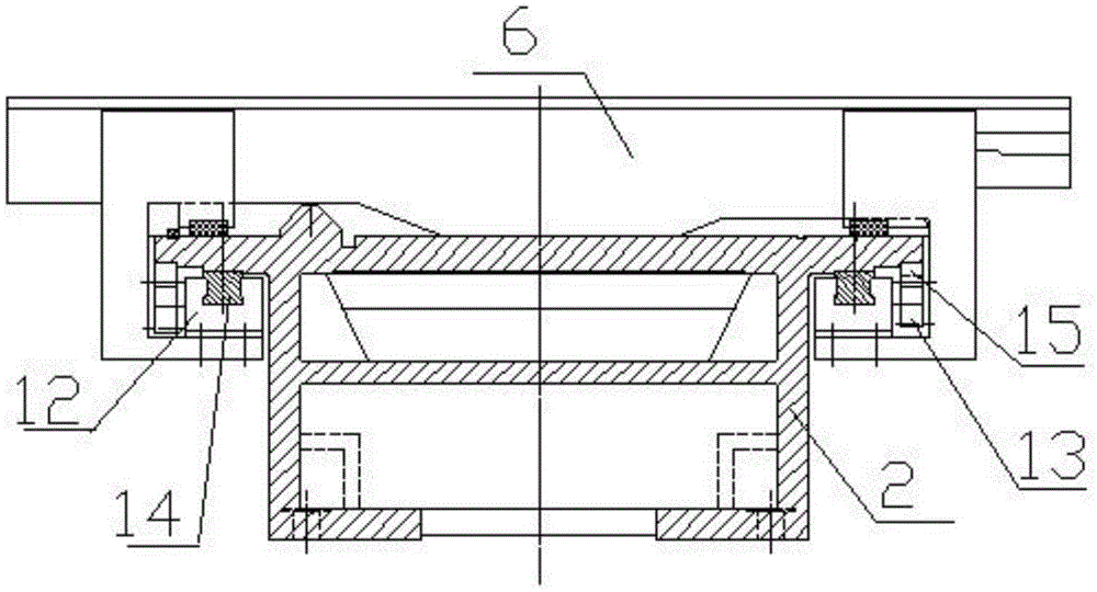
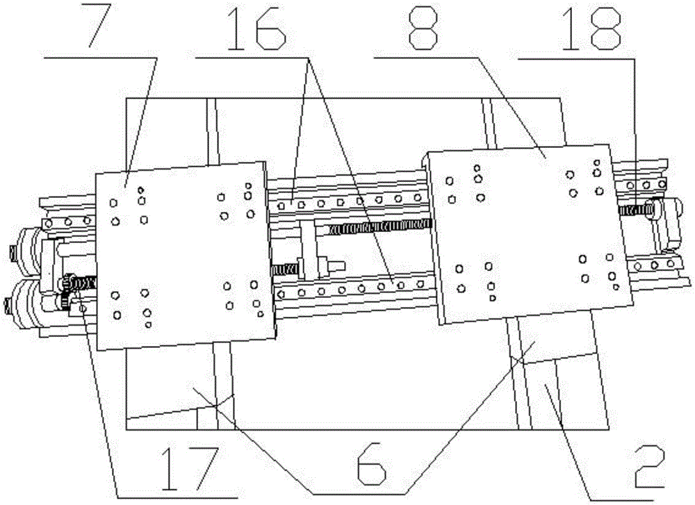
[0032] like figure 1 and figure 2 As shown, a special rubber grinding machine for rubber rollers includes a bedside 1 and a bed 2 connected in sequence, the bedside 1 is provided with a headstock 3, the bedside 2 is provided with a tailstock 4, and a workpiece 5 Fixed between the headstock 3 and the tailstock 4, the bed 2 below the workpiece 5 is provided with a large carriage 6, the large carriage 6 is provided with a slider 12 and a gear 13, and the bed 2 is provided with The first linear guide rail 14 and the rack 15, the slide block 12 cooperates with the first linear guide rail 14, the gear 13 cooperates with the rack 15, and the large carriage 6 is provided with In the front middle carriage 7 and the rear middle carriage 8, a knife rest 9 is installed on the front middle carriage 7, and an abrasive belt grinder 10 is installed on the rear middl...


PUM


Abstract

The invention discloses a special automobile rubber grinding machine for a rubber covered roller. The special automobile rubber grinding machine comprises a lathe head and a lathe bed which are sequentially connected, wherein the lathe head is provided with a headstock, the lathe bed is provided with a tailstock, and a workpiece is fixed between the headstock and the tailstock; the lathe bed below the workpiece is provided with a large planker, a sliding block and a gear are arranged on the large planker, the lathe bed is provided with a linear guide rail and a rack, the sliding block is matched with the linear guide rail, and the gear is matched with the rack; the large planker is provided with a premedial planker and a postmedial planker which can move on the large planker, the premedial planker is provided with a knife rest, and the postmedial planker is provided with a belt sanding machine. According to the special automobile rubber grinding machine, the firmness between a bonding agent and a central spindle can be guaranteed, a traditional sand blasting technology can be replaced, and the surface is not needed to be washed by any solvent, so that the balance of the central spindle can not be damaged, the production efficiency can be improved, the cost is reduced and the labor force is saved, and the key is that the bonding between the rubber and the central spindle can be reliably guaranteed. According to the special automobile rubber grinding machine, the consumable materials can be saved and the environment pollution can be reduced.

Description

technical field [0001] The invention relates to a special equipment for manufacturing rubber rollers, in particular to a special grinding machine for vehicle rubber. Background technique [0002] The steel core treatment of the rubber roller before coating is an important link in the production process of the rubber roller. How to simplify the operation process, reduce the cost and ensure the quality is the most basic process of the rubber roller production, which involves the adhesion of the rubber layer and the stability of the center of gravity. other key quality characteristics. [0003] The traditional steel core surface treatment process is sandblasting and surface threading. The former process has disadvantages such as high labor intensity, high cost, and dust pollution in the operating place. The latter process will destroy the dynamic balance and steel core of the original steel core. Rigidity and other shortcomings. [0004] Simultaneously the processing technolo...

Claims


Application Information

Patent Timeline
Patent Type & Authority Patents(China)
IPC IPC(8): B23P23/02B23Q1/26B23Q1/01B23B27/00
Inventor 潘建国
Owner JINAN POWER RUBBER ROLLER EQUIP
Why Eureka
Try Eureka