Electroosmosis sludge dewatering equipment

A sludge dewatering machine and sludge dewatering technology, applied in the direction of dehydration/drying/concentrated sludge treatment, etc., can solve the problems of high cost, complex equipment structure, failure to fully utilize electroosmosis, etc., and achieve the effect of simple structure

Active Publication Date: 2013-10-02
浙江科力尔环保设备股份有限公司
View PDF4 Cites 14 Cited by
  • Summary
  • Abstract
  • Description
  • Claims
  • Application Information

AI Technical Summary

Problems solved by technology

In recent years, a variety of electro-osmotic dehydration equipment has emerged, including electro-osmotic belt dehydration machines, drum-type electro-osmotic dehydration machines, etc. However, due to the structural limitations of dehydration equipment, electro-osmotic dehydration is used to treat Sludge is still not widely accepted by the market due to high cost, failure to meet incineration requirements after treatment, or low production capacity
Looking at the existing sludge dewatering machines, basically a mesh belt is set between the two electrodes, and the effect of electroosmosis cannot be fully exerted. For example, the electroosmotic belt press sludge dewatering equipment disclosed in Chinese invention patent publication CN 102653488A , not only the equipment structure is complicated, but also can only make the water content of the sludge cake after pressing less than 60%

Method used


Image

  • Electroosmosis sludge dewatering equipment
  • Electroosmosis sludge dewatering equipment
  • Electroosmosis sludge dewatering equipment

Examples


Embodiment Construction

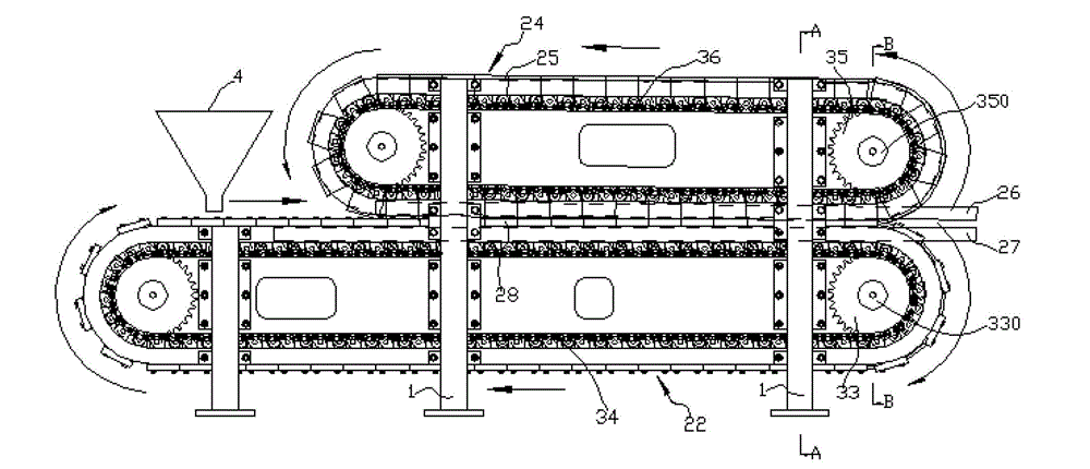
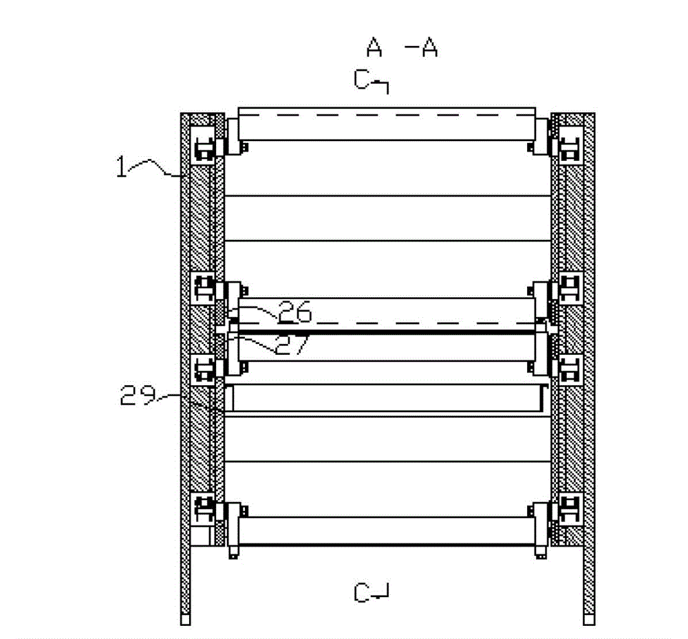
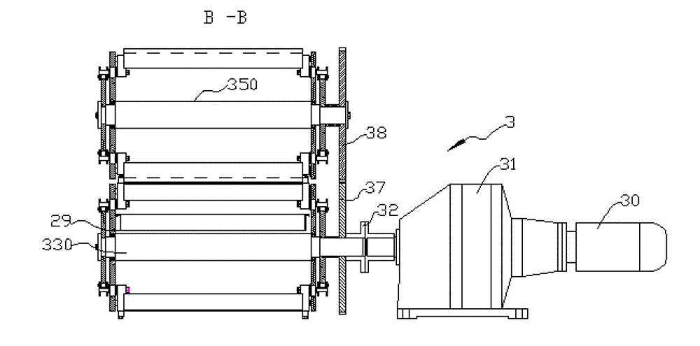
[0029] Such as Figure 1 to Figure 10 As shown, the electroosmotic sludge dewatering machine provided in this embodiment mainly includes a frame 1, a sludge dewatering device 2, a driving mechanism 3, a power supply (not shown in the figure), a feeding hopper 4, and a scraper 5. The specific structures of the sludge dewatering device 2 and the drive mechanism 3 will be described in detail below.

[0030] In this example, the sludge dewatering device 2 includes an annular upper guide rail 20 fixed on the frame 1, an annular lower guide rail 21 fixed on the frame 1 and located below the annular upper guide rail 20, a plurality of screen trolleys 22, a plurality of The moving net plate 23 , a plurality of extruding trolleys 24 , a plurality of extruding plates 25 , conductive plates 26 , 27 and a sewage pan 29 located below the moving net plate 23 . The centerlines of the annular upper guide rail 20 and the annular lower guide rail 21 extend along the horizontal direction, t...


PUM


Abstract

The invention relates to electroosmosis sludge dewatering equipment. The electroosmosis sludge dewatering equipment comprises a frame, a sludge dewatering device, a driving mechanism, a power supply, an annular upper guide rail and an annular lower guide rail fixed on the frame, a plurality of mobile net plates which are capable of moving along the track of the annular lower guide rail, a plurality of extruding plates which are capable of removing along the track of the annular upper guide rail. The tracks of the lower part of the annular upper guide rail and the upper part of the annular lower guide rail are linear. The mobile net plates and the extruding plates are made of conductive materials, and are connected with the cathode and the anode of the power supply respectively; and a sludge extruding channel is formed between the mobile net plates which are arranged on the linear track of the annular upper guide rail and the extruding plates which are arranged on the linear track of the annular lower guide rail, and the width of the sludge extruding channel is narrowed down gradually from one end to the other end. The electroosmosis sludge dewatering equipment is capable of taking full advantage of electroosmosis, and decreasing water content of squeezed sludge cake to 50% or even lower than 40%. In addition, the structure of the electroosmosis sludge dewatering equipment is simple.

Description

technical field [0001] The invention relates to a sludge dewatering device, in particular to an electroosmotic sludge dewatering machine. Background technique [0002] With the development of social economy and the acceleration of urbanization, the amount of urban sewage treatment plants and the accompanying sludge has increased rapidly. According to relevant materials, in 2010, the sludge produced by my country's sewage treatment plants reached 300 million tons. Because sludge contains a large amount of cell water, at present, almost all the existing equipment and technology of sewage treatment plants can only reduce the moisture content of sludge to about 80%. More than 50% will cost a lot of money, so almost all sewage treatment plants in our country often can only use sludge as landfill and pile up, which has caused serious environmental pollution problems. Using the principle of electro-osmotic dehydration to treat the sludge, it can be seen from the experimental data...

Claims


Application Information

Patent Timeline
Patent Type & Authority Applications(China)
IPC IPC(8): C02F11/12
Inventor 黄海
Owner 浙江科力尔环保设备股份有限公司
Why Eureka
Try Eureka