Fluid conveying device and method

A fluid conveying and fluid technology, applied in the field of fluid conveying devices, can solve the problems of complex control part, high equipment cost, huge system, etc., and achieve the effect of reducing volume, small volume and low energy consumption

Inactive Publication Date: 2013-10-02
华国红
View PDF7 Cites 2 Cited by
  • Summary
  • Abstract
  • Description
  • Claims
  • Application Information

AI Technical Summary

Problems solved by technology

At present, the existing piston pumps all use the hydraulic system to push the piston to work. This kind of hydraulic delivery pump uses the power machine to drive the liquid pump to inject the pressure liquid into the pressure cylinder, and pushes the piston to move through the connecting rod. The material is conveyed by internal movement, while the plunger pump relies on the reciprocating movement of the plunger in the cylinder to change the volume of the sealed working chamber to realize oil absorption and oil pressure. The plunger is driven by the eccentric rotation of the pump shaft. Reciprocating motion, its suction and discharge valves are one-way valves, when the plunger is pulled outward, the pressure in the working chamber is reduced, the outlet valve is closed, when the pressure is lower than the inlet pressure, the inlet valve is opened, and the

Method used


Image

  • Fluid conveying device and method
  • Fluid conveying device and method
  • Fluid conveying device and method

Examples


Embodiment 1

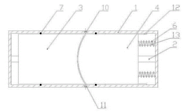
[0024] Such as figure 1 , figure 2As shown, in this embodiment, the rotation of an active element in the same cavity causes the position of a reciprocating element to move axially to form a volume to absorb fluid from the upstream side of the delivery direction or deliver the fluid to the downstream side for discharge. The end surfaces of the active element and the reciprocating element are both curved surfaces with at least one protrusion and at least one depression, and when the protrusion of the active element is located in the depression of the reciprocating element, they are in contact with each other; when the active The protruding part of the element can form a volume when it contacts the protruding part of the reciprocating element. As a preferred solution, the end faces of the active element and the reciprocating element are convex curved surfaces or concave curved surfaces. When the convex curved surface The volume is formed when the top arc contacts the top arc of...

Embodiment 2

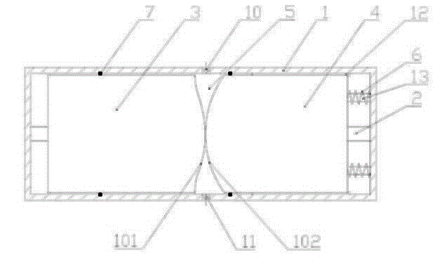
[0026] Such as image 3 , Figure 4 As shown, in this embodiment, the rotation of one active element is used in the same cavity to make the positions of the two reciprocating elements move axially respectively to form a volume, so as to suck fluid from the upstream side of the delivery direction and deliver the fluid to the downstream side Exhaust, the end surfaces of the active element and the reciprocating element are both curved surfaces with at least one protrusion and at least one depression, and when the protrusion of the active element is located in the depression of the reciprocating element, they fit together. A volume can be formed when the protrusion of the active element is in contact with the protrusion of the reciprocating element. As a preferred solution, the end faces of the active element and the reciprocating element are convex curved surfaces or concave curved surfaces. When the convex The volume is formed when the top arc of the curved surface is in contac...

Embodiment 3

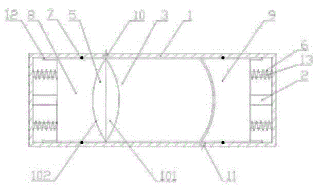
[0028] Such as Figure 5 , Figure 6 As shown, this embodiment is roughly the same as Embodiment 2, the difference is that instead of using a power shaft in this embodiment, a linkage shaft and an additional power device are used to rotate the rotating element 3, specifically , the fluid delivery device includes a cylinder 1, a linkage shaft 20 that is located in the cylinder 1 and rotates with the cylinder 1; a first sliding reciprocating piston 8 that is sequentially arranged on the linkage shaft 20 from front to back , a rotating element 3 adapted to the first sliding reciprocating piston 8 and a second sliding reciprocating piston 9 adapted to the rotating element 3, the rotating element 3 slidingly fits with the linkage shaft 20, and The rotating element 3 is provided with a one-way channel, the first sliding reciprocating piston 8 is synchronously linked with the second sliding reciprocating piston 9 through the linkage shaft 20, and the outer peripheral surface of the ...


PUM


Abstract

The invention discloses and provides a fluid conveying device which is simple in structure, smaller in volume, lower in energy consumption, and convenient to operate, and a method. The method is characterized in that a volume is formed after at least one driving element rotates to allow a position of at least one reciprocation element to be moved axially in the same cavity, in order to suck a fluid from an upstream side of a conveying direction or convey the fluid to a downstream side to be discharged; each of the end faces of the driving element and the reciprocation element is a curved surface with at least one bulge and at least one sunk part; when the bulge of the driving element is positioned in the sunk part of the reciprocation element, the driving element is bonded with the reciprocation element; and when the bulge of the driving element is contacted with the bulge of the reciprocation element, the volume is formed after the reciprocation element is moved axially. The fluid conveying device comprises a cylinder body, a power shaft positioned in the cylinder body, a rotating element arranged on the power shaft, and a sliding reciprocation piston adapted to a rotating piston, wherein a suction inlet and a discharge outlet are formed in the cylinder body, and when the rotating element rotates, the rotating element allows the sliding reciprocation piston to move axially on the power shaft, and the suction inlet is communicated with the discharge outlet after the volume is formed.

Description

technical field [0001] The present invention relates to a fluid delivery device and method. Background technique [0002] The pump is controlled by the prime mover, drives the medium to move, and is an energy conversion device that converts the energy output by the prime mover into the pressure energy of the medium. Pumps are mainly used to transport liquids, including water, oil, acid-base liquids, emulsions, suspoemulsions, and liquid metals; they can also transport liquids, gas mixtures, and liquids containing suspended solids. According to the working principle, it can be divided into three categories: 1. Positive displacement pumps, which rely on the movement of the working parts to periodically increase and decrease the working volume to absorb and discharge liquid, and directly increase the pressure of the liquid by the extrusion of the working parts; 2. 1. The impeller pump relies on the impeller to drive the liquid to rotate at a high speed to transfer the mechanic...

Claims


Application Information

Patent Timeline
IPC IPC(8): F04B43/04
Inventor 华国红
Owner 华国红
Why Eureka
Try Eureka