Sintering waste heat power generation exhaust gas recycling utilization system

A technology of waste heat power generation and hot exhaust gas, applied in waste heat treatment, lighting and heating equipment, furnaces, etc., can solve problems such as dust pollution, limited heat exchange capacity of exchangers, waste of air volume, etc., to eliminate waste of heat energy and improve the working environment of employees Effect

Inactive Publication Date: 2013-10-02
LIUZHOU IRON & STEEL
View PDF6 Cites 5 Cited by
  • Summary
  • Abstract
  • Description
  • Claims
  • Application Information

AI Technical Summary

Problems solved by technology

[0002] At present, in the domestic production process of sintering waste heat power generation, the high-temperature hot exhaust gas collected from the annular cooler passes through the heat exchanger for heat exchange and recovery, and then becomes low-temperature hot exhaust gas, which is directly discharged through the external chimney. This method has the following disadvantages : 1. Due to the limited heat exchange capacity of the exchanger, after the high-temperature hot exhaust gas collected from the annular cooler passes through the heat exchanger, a large amount of heat is brought into the atmosphere along with the low-temperature hot exhaust gas discharged outside, which not only causes waste of ...

Method used


Image

  • Sintering waste heat power generation exhaust gas recycling utilization system

Examples


Embodiment Construction

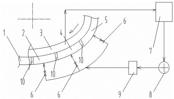
[0017] Such as figure 1 As shown, the cooling air ducts of the high-temperature section of the ring cooling are divided into sections (according to the air duct regions corresponding to the high-temperature sinter in the three temperature regions of 320~400℃, 400~500℃, and 500℃) to realize the high-temperature sintering Sectional cooling, that is, the annular cooling air duct 1 is divided into the corresponding first section cooling duct 5, the second section cooling duct 4, and the third section cooling duct 3 by the three air duct partitions 10, the first section Cooling air duct 5 corresponds to the ring-cooled high-temperature sinter layer area above 500℃, the second cooling air duct 4 of the ring-cooled high-temperature section corresponds to the 400-500℃ ring-cooled high-temperature sinter layer area, and the third cooling air duct 3 of the ring-cooled high-temperature section corresponds to 320~400℃ ring cold high temperature sinter layer area.

[0018] A heat exchanger 7...


PUM


Abstract

Provided is a sintering waste heat power generation exhaust gas recycling utilization system. The system is characterized in that the system is provided with a heat exchanger, heat recovery is carried out on annular cooling high-temperature hot exhaust gas collected from an annular cooling high-temperature section hot air hood, at least three air duct partition boards are arranged on an annular cooling air duct, and the air duct partition boards divide the annular cooling air duct into corresponding cooling air ducts. Low-temperature hot exhaust gas produced after heat exchange carried out through the heat exchanger is respectively or simultaneously sent into the cooling air ducts to form a sealed air circulation which collects and sends the low-temperature hot exhaust gas which is obtained through heat exchange and cooling of the annular cooling high-temperature hot exhaust gas into the cooling air ducts. The system has the advantages that the low-temperature hot exhaust gas generated by sintering annular cooling waste heat power generation is recycled, heat energy waste and environment pollution phenomena caused by the exhausted low-temperature hot exhaust gas are eliminated, working environment of workers is substantially improved, sintering annular cooling waste heat power generation amount can be improved by 30% through collection and recycling of the exhaust gas in power generation, investment cost is significantly reduced, and electricity consumption in production is reduced by 26,880 thousand kw.h per day.

Description

Technical field [0001] The invention relates to the recovery and utilization of high-temperature sintering waste heat, in particular to a sintering waste heat power generation heat waste gas recycling system. Background technique [0002] In the current domestic production process of sintering waste heat power generation, the high-temperature hot exhaust gas collected from the ring cooler is converted into low-temperature hot exhaust gas after heat exchange and recovery through a heat exchanger, which is directly discharged through the external exhaust chimney. This method has the following disadvantages :1. Due to the limited heat exchange capacity of the heat exchanger, after the high-temperature hot exhaust gas collected from the annular cooler passes through the heat exchanger, a large amount of heat is carried into the atmosphere with the low-temperature hot exhaust gas discharged outside, which not only causes a waste of energy, but also Causes serious heat pollution to th...

Claims


Application Information

Patent Timeline
IPC IPC(8): F27D17/00
Inventor 王恒杨鹏陈有升陈海燕李伟林卢福德吴丹伟刘巍向小平孙火荣谢运强舒良良
Owner LIUZHOU IRON & STEEL
Why Eureka
Try Eureka