An antenna radiation unit and an electricity feeding method

An antenna radiation and power feeding technology, applied in the field of communication, can solve problems such as complex structure, unbalanced cables, and difficulty in controlling the consistency of vibrator units

Active Publication Date: 2013-10-02
GUANGDONG BROADRADIO COMM TECH
View PDF4 Cites 8 Cited by
  • Summary
  • Abstract
  • Description
  • Claims
  • Application Information

AI Technical Summary

Problems solved by technology

This solution can better realize the impedance matching of the unit broadband, but it contains a large number of components and has a complex structure; if it is mass-produced, the consistency of the vibrator unit is difficult to control
It feeds the dipoles through coupling feeding, which can easily lead to unbalanced cables on both sides of the radiating arm of a single dipole, which will eventually affect the radiation unit pattern of the entire dual-polarized antenna

Method used


Image

  • An antenna radiation unit and an electricity feeding method
  • An antenna radiation unit and an electricity feeding method
  • An antenna radiation unit and an electricity feeding method

Examples


Embodiment 1

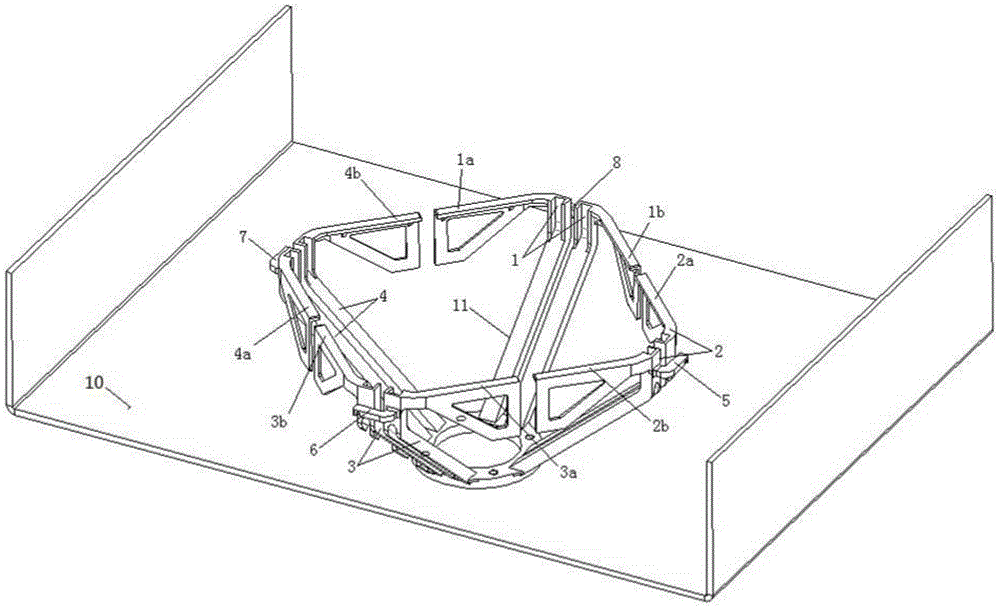
[0031] Such as figure 1 As shown, an antenna radiating unit 11 provided by an embodiment of the present invention is used to be installed on a metal reflector 10 to form a mobile communication base station antenna. Wherein, the antenna radiating unit 11 includes two pairs of dipole radiating units with orthogonal polarization, and each dipole radiating unit is respectively installed on the metal reflector 10 through a balun (balanced-unbalanced converter) . Each dipole radiating unit respectively includes two unit arms symmetrically fixed on the balun. Wherein, each balun includes two supporting columns arranged in parallel and adjacently, and the two unit arms in each dipole radiating unit are symmetrically fixed on the two supporting columns respectively.

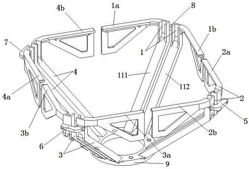
[0032] Specifically, in the embodiment of the present invention, the first unit arm 1a and the second unit arm 1b are fixed on the first balun 1, the third unit arm 2a and the fourth unit arm 2b are fixed on the second ...

Embodiment 2

[0041] Such as Figure 4 As shown, the embodiment of the present invention is a modified structure of the first embodiment. The first to fourth baluns in the embodiment of the present invention are not integrated through a base, but are separately installed on the metal reflector.

[0042] Other structures of this embodiment of the present invention are the same as those of Embodiment 1, and will not be repeated here.

Embodiment 3

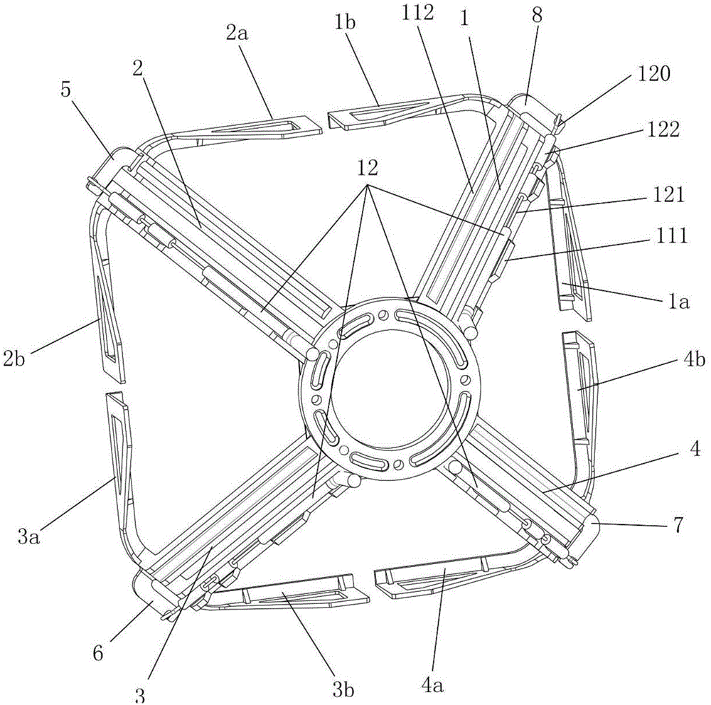
[0044] Such as Figure 5 As shown, the embodiment of the present invention is a modified structure of the first embodiment. In each dipole radiation unit in the embodiment of the present invention, the angle between the two unit arms fixedly connected to the upper end of the balun is an obtuse angle, so that the projection shape of all the unit arms on the reference plane is a center-symmetrical polygon. It should be noted that, in combination with Embodiment 1, the included angles between the two unit arms in each dipole radiation unit in the present invention can be various angles, and the projection of the unit arms on the reference plane can also be a curve, only the final guarantee It is sufficient that the projections of all unit arms on the reference plane enclose a centrally symmetrical polygon or circle.

[0045] In particular, in the embodiment of the present invention, the coaxial cable 12 whose characteristic impedance is Z1 is selected. The inner conductor 120 o...


PUM


Abstract

The invention relates to an antenna radiation unit. The antenna radiation unit comprises two dipole radiation units which are polarized and arranged in an orthogonal mode. Each dipole radiation unit is installed on a metal reflecting plate separately through a balun. Each balun comprises two support columns which are arranged to be parallel with and adjacent to each other. Each dipole radiation unit comprises two unit arms which are respectively installed on the two support columns in a corresponding mode. A coaxial cable which is arranged along the balun is arranged inside each dipole radiation unit. An outer conductor of each coaxial cable is connected with one of the unit arms or a corresponding support column. An internal conductor of each coaxial cable is connected with the other one unit arm or the corresponding support column. Each coaxial cable is provided with one or a plurality of outer conductor resection areas. The antenna radiation unit provided by the invention is simple in structure, and is easy to install. The antenna radiation unit provides convenience for electricity feeding. The antenna radiation unit provided by the invention is also good in consistency and easy to produce. Furthermore, the impedance match problem of the broadband antenna unit is solved and the optimization of electrical performance of antennas is realized.

Description

technical field [0001] The invention relates to the communication field, in particular to an antenna radiation unit and a feeding method thereof. Background technique [0002] With the development of mobile communication technology, modern communication systems have put forward higher and higher requirements for the indicators of dual-polarized base station antennas, especially gain, bandwidth characteristics, and processing technology. [0003] The existing dual-polarized antenna units mainly adopt the following implementation schemes: the first one adopts two dipole antenna dipole structures with common points, interleaving and polarization orthogonality; the second one adopts the microstrip radiation unit , to achieve dual polarization through coupling or direct feeding; the third is to use two pairs of dipoles placed orthogonally to form an approximately square layout. [0004] In a commonly used network communication system, the most commonly used horizontal half-power...

Claims


Application Information

Patent Timeline
Patent Type & Authority Applications(China)
IPC IPC(8): H01Q19/10H01Q21/24H01Q1/36H01Q1/12H01Q1/50
Inventor 谭杰洪吴壁群
Owner GUANGDONG BROADRADIO COMM TECH
Why Eureka
Try Eureka