
Pulse separation and broadening structure based on polarization beam splitting

A pulse separation and polarization beam splitting technology, applied in the structure/shape of the active medium, laser parts, electrical components, etc., can solve the problems of system instability, nonlinear phase shift, unfavorable pulses, etc., to achieve simple optical path design, The effect of strong stability and cost reduction

Active Publication Date: 2013-10-02
CHONGQING HUAPU NEW ENERGY CO LTD
View PDF6 Cites 6 Cited by
  • Summary
  • Abstract
  • Description
  • Claims
  • Application Information

AI Technical Summary

Problems solved by technology

Common pulse stretching methods include the use of gratings, dispersion, nonlinearity, etc. These methods have certain shortcomings, for example, it is not easy to accurately control the amount of stretching or compression; the accuracy of the optical path is high, complex, and the system is unstable; it is not easy to be used in industrial production. Integration; it is difficult to obtain wider broadening for pulses with narrow spectrum, and it is difficult to broaden femtosecond or picosecond pulses with wide spectrum to nanosecond level; it is inevitable to introduce unfavorable pulse compression in the process of high-power optical fiber amplification non-linear phase shift etc.

Method used


Image

  • Pulse separation and broadening structure based on polarization beam splitting
  • Pulse separation and broadening structure based on polarization beam splitting
  • Pulse separation and broadening structure based on polarization beam splitting

Examples


Embodiment

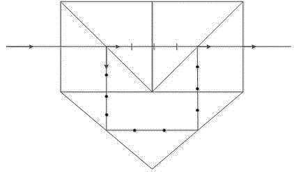
[0031] When the ultrashort pulse laser is injected into the unit structure, such as figure 1 As shown, it will be divided into P light vibrating parallel to the incident surface and S light vibrating perpendicular to the incident surface, resulting in the phenomenon of separation and broadening of the optical path. The block PBS is re-superimposed with the S light and exits. Because there is an optical path difference between the two beams of light, the two beams of light pulses are time-delayed to achieve the purpose of pulse splitting.

[0032] figure 1 It is a unit structure, two PBS are symmetrically bonded, and the lower part is a conical high-purity quartz crystal, where P light and S light are marked by short lines and dots respectively.

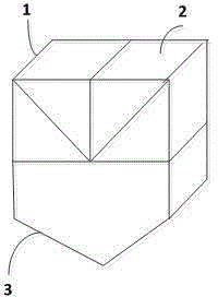
[0033] figure 2 It is a schematic diagram of the unit structure, composed of PBS1, PBS2, and conical quartz crystal 3, and the angle between the conical surfaces on both sides of the bottom is 45°.

[0034] In order to ensure that...


PUM


Abstract

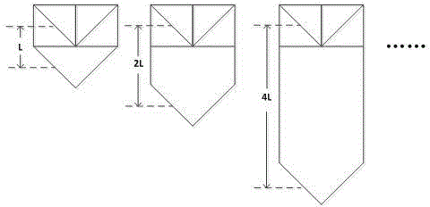
The invention discloses a pulse separation and broadening structure based on polarization beam splitting, which is formed by sequentially rotating angles of a plurality of unit structures in different lengths, bonding with optical cement or directly connecting an optical surface plated antireflection film, wherein each unit structure is formed by combining two identical polarization beam splitters and a tapered quartz crystal or glass; included angles of tapered surfaces on the two sides of the bottom of each unit structure are 45 degrees; in each unit structure, optical surfaces between the two identical polarization beam splitters and the tapered quartz crystal or the glass are coated with the antireflection films; the longitudinal lengths of the unit structures are doubled sequentially; and longitudinal distances among light beam incidence points in the unit structures are optical path differences after light paths are separated and broadened. The structure is applicable to broadening narrow-spectrum and wide-line pulses, can achieve pulse broadening in a nanosecond order, and is suitable for broadening the pulses in different and multiple bands simultaneously.

Description

technical field [0001] The invention belongs to the technical field of optical devices, and relates to a pulse separation and broadening structure based on polarization beam splitting, which is used for widening ultrashort laser pulses. Background technique [0002] Ultrashort laser pulses with high power and high repetition rate have broad application prospects in the fields of material processing, medical treatment, laser chemistry and high-energy physics, and pulse stretching and compression is one of the key technologies in the field of laser technology. Excessively high power pulses will cause damage to some optical devices, so using pulse stretching to reduce the peak power is one of the more common methods. After the power is amplified, the stretched pulse is compressed to obtain an ultrashort laser with high peak power pulse. [0003] Fiber lasers are the third generation of new lasers after traditional gas lasers and solid-state lasers. They have the advantages of ...

Claims


Application Information

Patent Timeline
Patent Type & Authority Applications(China)
IPC IPC(8): H01S3/067H01S3/11H01S3/10
Inventor 曾和平杨康文
Owner CHONGQING HUAPU NEW ENERGY CO LTD
Learn More