Constant current circuit of DC converter
A technology of DC converter and constant current, which is applied in the direction of conversion of DC power input to DC power output, output power conversion devices, instruments, etc. It can solve the problems of pull-down tube process and temperature deviation, and affect the accuracy of limiting current, so as to improve Response time, precise effect of limiting current
- Summary
- Abstract
- Description
- Claims
- Application Information
AI Technical Summary
Problems solved by technology
Method used
Image

Examples
Embodiment Construction
[0014] The present invention will be further described below in conjunction with the embodiments and the accompanying drawings.
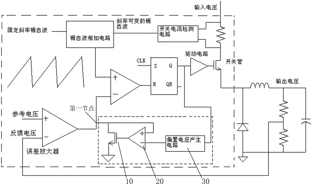
[0015] refer to figure 1 As shown, a constant current circuit of a DC converter, see the part surrounded by the dotted box in the figure, includes an operational amplifier 20 , a pull-down transistor 10 and a bias voltage generating circuit 30 . The output terminal of the error amplifier in the DC converter is the first node, which is connected to the drain of the pull-down tube 10 and the non-inverting input terminal of the operational amplifier 20, and the grid of the pull-down tube 10 is connected to the gate of the operational amplifier 20 At the output end, the source of the pull-down transistor 10 is grounded. The output terminal of the bias voltage generating circuit 3 is connected to the inverting input terminal of the operational amplifier 20, and the input terminal of the bias voltage generating circuit 3 is connected to the input termin...
PUM
 Abstract
Description
Claims
Application Information
 - Generate Ideas
- Intellectual Property
- Life Sciences
- Materials
- Tech Scout
- Unparalleled Data Quality
- Higher Quality Content
- 60% Fewer Hallucinations
Browse by: Latest US Patents, China's latest patents, Technical Efficacy Thesaurus, Application Domain, Technology Topic, Popular Technical Reports.
© 2025 PatSnap. All rights reserved.Legal|Privacy policy|Modern Slavery Act Transparency Statement|Sitemap|About US| Contact US: help@patsnap.com