Improvements in or relating to millimeter and sub-millimeter wave radar-radiometric imaging

A technology of radiation imaging and radar, which is applied in the reflection/re-radiation of radio waves, the device that makes the antenna work in different bands at the same time, and the use of re-radiation, etc., can solve the problem of limiting imaging speed, difficulty in positioning feeding components, and high total cost. problem, achieve the effect of eliminating uncertainty, improving information content and imaging speed

Inactive Publication Date: 2013-10-02
RADIO PHYSICS SOLUTIONS
View PDF4 Cites 18 Cited by
  • Summary
  • Abstract
  • Description
  • Claims
  • Application Information

AI Technical Summary

Problems solved by technology

[0015] Disadvantages of systems with beamforming matrices in the millimeter and submillimeter bands include: difficulties in positioning a large number of feed elements (measurement channels) in the focal plane of the antenna when physically limited dimensions of the unit feed elements exist; Problematic establishment of beamforming matrices with spatially overlapping beams when implementing highly directional antennas; and high overall cost of the system in the quadratic dependence B on the number of image elements B for each coordinate 2 aspect correlates with the incr

Method used


Image

  • Improvements in or relating to millimeter and sub-millimeter wave radar-radiometric imaging
  • Improvements in or relating to millimeter and sub-millimeter wave radar-radiometric imaging
  • Improvements in or relating to millimeter and sub-millimeter wave radar-radiometric imaging

Examples


Embodiment Construction

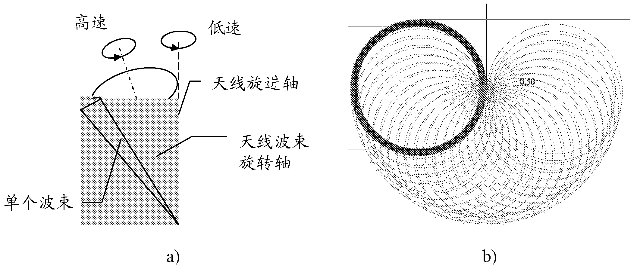
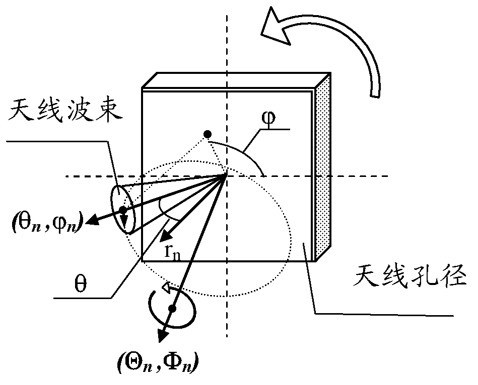
[0063] The proposed radar and radiometric imaging method will be implemented as follows (see Figure 1-3 , 4a, c).

[0064] A series of operations will be performed cyclically in time during time interval T (e.g., T=1 second) simultaneously or continuously during time interval 2T, forming two images - radar (AI) and radiometric (PI), For these two images, due to the antenna beam with T a (T a ≤T) (for example, T a = 0.1 s) period around an axis of rotation not coincident with any of its beam axes, thus a survey of a selected space segment is carried out at time interval T, during time T without interval using antenna positioning equipment by means of antenna Simultaneous variation of the spatial orientation of the axis of rotation (e.g. due to precession of the axis of rotation of the antenna along the generatrix of the cone, e.g. a cone with an apex angle of 10° and a fully precessed Duration T p for T p=T). In this case, the observed spatial element is radiated using ...


PUM


Abstract

An antenna is provided that is configured to implement a combined radar and radiometric imaging method. The antenna comprises: a bearing device on which is rigidly mounted: rotating waveguide adapter which provides the output for the antenna; an electromechanical drive, the output shaft of which is defined as the main axis of rotation for the antenna and a position sensor. The antenna further comprises an antenna rotor, the rotation of which is configured to be controlled by the out-put shaft of the electromechanical drive of the bearing device. The antenna rotor comprises: at least one 2D diffraction grating; planar dielectric waveguide connected over a diffraction field to the 2D diffraction grating; a linear waveguide turn; and a feed adapter.

Description

technical field [0001] The present invention relates to microwave imaging equipment and is designed to be used when operating in active (when transmitting a microwave signal and receiving a portion of this signal reflected from an observed object) and / or passive (when receiving natural external emissions) modes On-line millimeter or submillimeter wave imaging of objects. The method, as well as the antenna and system implementing the method, can be used in particular to obtain images of people during customs supervision, to detect various objects on the human body hidden under clothing, or to measure temperature for medical diagnosis. Background technique [0002] Currently, remote surveys of various environments are frequently performed using methods (passive and active) implemented in the microwave band. These methods are based on the correlation between the intensity (in passive mode) or backscattering values ​​(in active mode) of the intrinsic radiation-thermal radiation...

Claims


Application Information

Patent Timeline
IPC IPC(8): H01Q3/10H01Q13/28H01Q25/00H01Q21/06H01Q5/00G01S13/42G01S13/48G01S13/86G01K11/00H01Q5/20H01Q5/22
CPCG01S13/89G01K11/006G01S7/292G01S13/422H01Q3/10H01Q5/20H01Q5/22H01Q5/50H01Q13/28H01Q21/068H01Q25/00H01Q25/002
Inventor S·夏罗Y·希德兰克D·惠勒D·敦唐纳德
Owner RADIO PHYSICS SOLUTIONS
Why Eureka
Try Eureka