Electromagnetic relay testing equipment and method

A technology for electromagnetic relays and testing equipment, applied in circuit breaker testing and other directions, can solve the problems of no software processing and prediction, detection accuracy problems, and limited life of relays, and achieve the effect of eliminating influence and improving life.

Inactive Publication Date: 2013-10-09
中国人民解放军第二炮兵装备研究院第三研究所
View PDF4 Cites 34 Cited by
  • Summary
  • Abstract
  • Description
  • Claims
  • Application Information

AI Technical Summary

Problems solved by technology

[0003] The existing detection methods mainly have the following deficiencies: (1) During detection, the load current of the electromagnetic relay is usually a specified value such as 0.5A, 1A, which meets the requirements of the national standard, but it is far less than the rated load current of the electromagnetic relay, and the electromagnetic relay cannot be tested at the limit. The electrical performance under certain conditions is not conducive to evaluating its reliability; (2) The circuit of the detection instrument itself uses a relay, which has problems in detection accuracy, and the life of the relay is limited, and it is a vulnerable part. When it is used frequently, it needs to be replaced frequently; (3) The test results only contain the data obtained from the actual test, without software processing and prediction

Method used


Image

  • Electromagnetic relay testing equipment and method
  • Electromagnetic relay testing equipment and method
  • Electromagnetic relay testing equipment and method

Examples


Embodiment 1

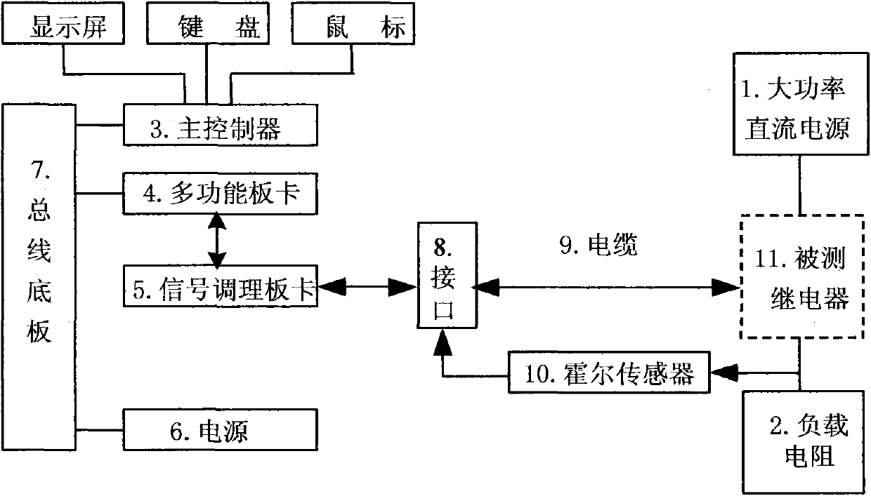
[0036] Embodiment 1: referring to accompanying drawing, a kind of electromagnetic relay detection equipment comprises: power supply 6, bus backplane 7, interface 8, the cable 9 that connects described interface 8 and tested relay 11 pins; It is characterized in that: it also includes : High-power DC power supply 1, load resistance 2, main controller 3, multi-function board 4, signal conditioning board 5, Hall sensor 10;

[0037] The high-power DC power supply 1 is used to provide the voltage and current required for contact detection of the relay 11 under test, the output voltage is adjustable, and the maximum output current is not less than 50A; its positive output terminal is connected to the common contact of the relay 11 under test. end;

[0038] The load resistance 2 is connected between the normally open contact of the measured relay 11 and the negative output terminal of the high-power DC power supply 1; the load resistance 2 is a combination of resistance wires with in...

Embodiment 2

[0043] Embodiment 2: a kind of electromagnetic relay detection method, it uses the electromagnetic relay detection equipment described in embodiment 1, and comprises the following steps:

[0044] A. Detection action time

[0045] According to the nominal operating time of the relay under test 11, the counting frequency and the operating mode of the multi-function board 4 timers are configured by the main controller 3 to make it ready for counting; according to the nominal value of the relay under test 11 Coil rated operating voltage, the main controller 3 controls the relay coil detection circuit, so that the voltage drop on the coil of the relay 11 under test is the rated operating voltage, and at the same time, the main controller 3 reports to the designated register of the timer Write the initial value of the count to make it start counting; by continuously querying the normally closed contact signal and the normally open contact signal, the query value and count value are ...


PUM


Abstract

The invention belongs to the technical field of testing electrician devices, and particularly relates to the testing of an electromagnetic relay. Electromagnetic relay testing equipment comprises a power source (6), a bus baseboard (7), an interface (8) and a cable (9) for connecting the interface (8) with a pin of a tested relay (11), and the equipment is characterized by also comprising a high-power direct-current power source (1), a load resistor (2), a main controller (3), a multifunctional board card (4), a signal conditioning board card (5) and a hall sensor (10). The electromagnetic relay testing equipment has the main advantages that 1. during testing, a contact of the tested relay works at rated load current, so that a reliable testing conclusion can be given; 2. transistor devices such as triodes and field-effect tubes are used for controlling the electromagnetic relay to act and switch signals, so that the influence of action delaying on testing results is eliminated, and the service life of the testing equipment is prolonged; 3. the parameter variation of the electrical property of the tested relay can be forecasted so as to provide the basis for application.

Description

technical field [0001] The invention belongs to the technical field of electrical device testing, in particular to electromagnetic relay testing. Background technique [0002] Before the electromagnetic relay is put into use, it is often necessary to test its electrical performance parameters to evaluate whether it meets the requirements for use. There are two main types of existing detection methods: one is to monitor one or several parameters and conduct multiple tests in a cycle, and the results obtained can be used to judge the electrical life of the electromagnetic relay; the other is to perform one-time detection of multiple parameters , the obtained results can be used to judge the current performance state of the electromagnetic relay. [0003] The existing detection methods mainly have the following deficiencies: (1) During detection, the load current of the electromagnetic relay is usually a specified value such as 0.5A, 1A, which meets the requirements of the nat...

Claims


Application Information

Patent Timeline
Patent Type & Authority Applications(China)
IPC IPC(8): G01R31/327
Inventor 刘政波李智吴勇军吴金才李晓建余维荣
Owner 中国人民解放军第二炮兵装备研究院第三研究所
Why Eureka
Try Eureka