Gate driven by cam structure

A technology of cams and turnstiles, which is applied in the field of turnstiles driven by cam structures, can solve the problems of affecting the service life of the mechanism, high equipment cost, and difficulty in speed control, so as to reduce equipment costs, keep the position unchanged, and prevent pedestrians from entering the turnstile Effect

Active Publication Date: 2013-10-16
浙江众合科技股份有限公司
View PDF6 Cites 5 Cited by
  • Summary
  • Abstract
  • Description
  • Claims
  • Application Information

AI Technical Summary

Problems solved by technology

[0002] Existing gates usually use a link mechanism as the connecting device for opening and closing the door panel. When the motor drives the door panel to open and close through the link mechanism, due to the transmission characteristics of the link mechanism, there is a gap between the rotation speed of the door panel and the output speed of the motor. The conversion is compli

Method used


Image

  • Gate driven by cam structure
  • Gate driven by cam structure
  • Gate driven by cam structure

Examples


Embodiment 1

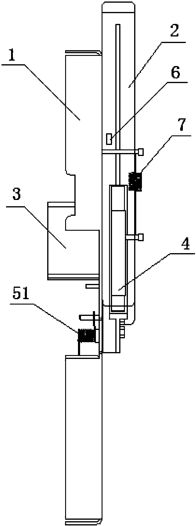
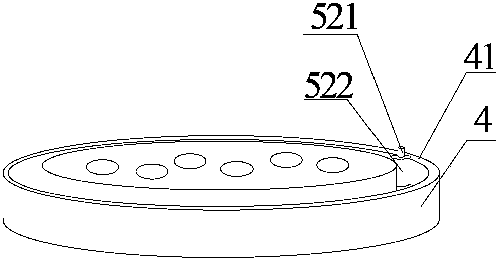
[0041] Such as Figure 5-6 As shown, the position sensor includes a photoelectric encoder 61, and the photoelectric encoder 61 includes a photoelectric code disc. The photoelectric code disc is set on the hinged end of the door panel 2 and the frame 1 and rotates with the opening and closing of the door panel 2. . The control unit presets the angle that the door panel 2 turns when the door is opened and closed, detects the real-time turned angle of the door panel 2 through the photoelectric code disc, and sends the detected angle information of the door panel 2 to the control unit. If the cam 4 is worn out, the door panel 2 cannot reach the preset angle of the door opening and closing state, and the motor 3 drives the cam 4 to rotate and continue to rotate until the control unit receives the signal that the door panel 2 switch is in place and stops rotating, keeping the door panel 2 open and closed The door position is always in place. The photoelectric encoder 61 has high t...

Embodiment 2

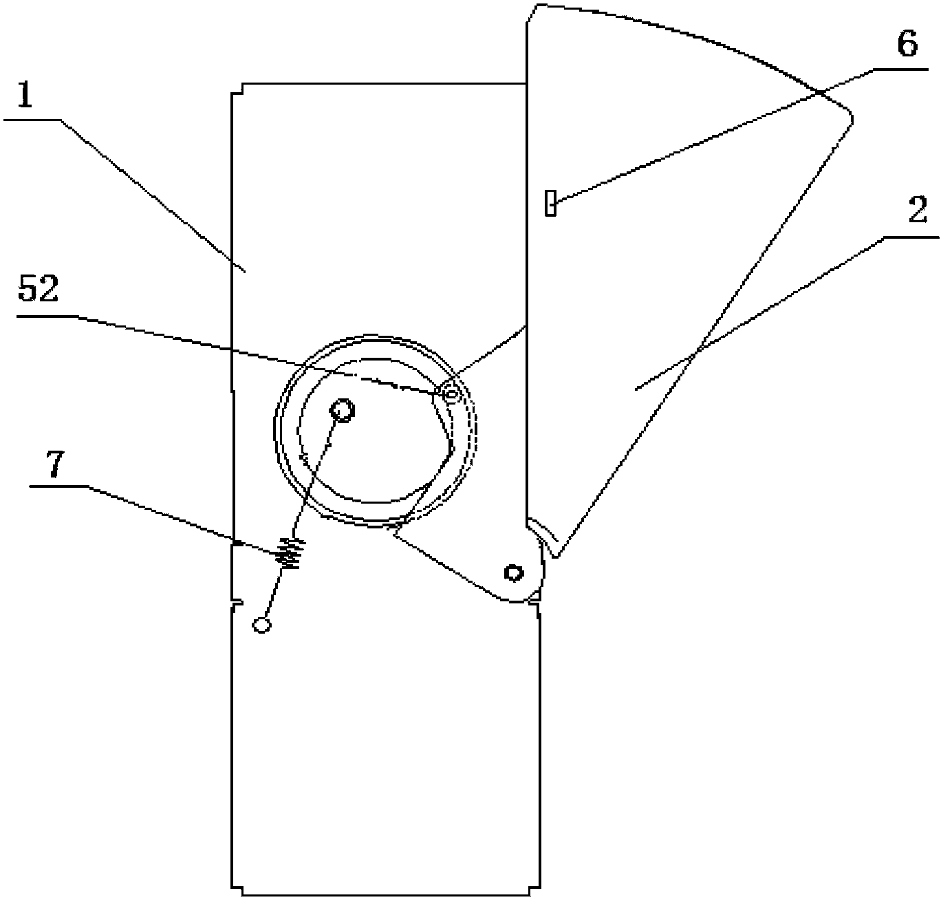
[0043] Such as Figure 7-8 As shown, the position sensor 6 includes a travel switch 62, and the frame 1 is provided with two limit rods 11, and the limit rod 11 cooperates with the travel switch 62 to control the opening and closing position of the door panel 2. limit. There is a limit rod 11 at the position of door opening and door closing, and the signal of whether it is in place is sent to the control unit through the travel switch 6. When the travel switch 62 touches the limit rod 11, the travel switch 62 sends an in-position command to the control unit. The control unit sends a control command to the motor 3, and the motor 3 stops rotating. When the cam 4 wears out, the control unit cannot receive the signal that the switch of the door panel 2 is in place, and the motor 3 drives the cam 4 to continue to rotate until the control unit receives the signal that the switch of the door panel 2 is in place and stops rotating, so as to keep the door panel 2 in the open and close...


PUM


Abstract

The invention discloses a gate driven by a cam structure. The gate driven by the cam structure comprises a machine frame, a gate plate and a motor. The motor is fixed on the machine frame, the gate plate is hinged to the machine frame, a cam is sleeved on a rotary shaft of the motor, the motor drives the cam to rotate, a locking device used for being matched with the cam in operation is arranged between the cam and the gate plate, and the cam drives the gate plate to open and close under the coordination of the locking device. A link mechanism is used for driving the gate plate to close and open by most current gates, a speed feedback device and a control system need to be additionally arranged to achieve the ideal speed curve needed by the gate plate, the cost of the device is high, noise can be generated if the link mechanism is installed inappropriately, and the service life of the link mechanism is influenced. Due to the simple control of the motor, control over the opening and closing speed of the gate plate identical to the ideal gate opening and gate closing speed suitable for normal passing speed of passengers is achieved, installation is simple, and cost is low.

Description

technical field [0001] The invention relates to a gate device, in particular to a gate driven by a cam structure. Background technique [0002] Existing gates usually use a link mechanism as the connecting device for opening and closing the door panel. When the motor drives the door panel to open and close through the link mechanism, due to the transmission characteristics of the link mechanism, there is a gap between the rotation speed of the door panel and the output speed of the motor. The conversion is complicated, and the speed control is difficult. In order to adapt the speed of the door panel to the walking speed of pedestrians, the speed of the motor needs to be adjusted through the speed feedback device and the control system, resulting in high equipment costs and improper installation of the linkage mechanism. It is easy to generate noise and affect the service life of the mechanism. Contents of the invention [0003] The problem to be solved by the present inve...

Claims


Application Information

Patent Timeline
IPC IPC(8): E01F13/06
Inventor 刘丹丹陈祥献陈峰陈森炎
Owner 浙江众合科技股份有限公司
Why Eureka
Try Eureka