Frequency-shifting super-resolution microscopic imaging method and device based on microstructure

A micro-imaging and micro-structure technology, applied in microscopes, optics, instruments, etc., can solve problems such as complex system structure, inability to use non-fluorescent samples, and limited range of use, achieving high resolution fineness and high image refresh rate , strong applicability

Inactive Publication Date: 2015-11-11
ZHEJIANG UNIV
View PDF6 Cites 0 Cited by
  • Summary
  • Abstract
  • Description
  • Claims
  • Application Information

AI Technical Summary

Problems solved by technology

The electron microscopic imaging technology developed in the 1930s and various non-optical probe scanning microscopic imaging technologies that emerged in the early 1980s have nanometer or even higher resolution capabilities, but they exist to varying degrees. The complex structure of the system, the harsh requirements of the imaging and detection environment, and the cumbersome sample processing are difficult, especially the important optical information of the sample (such as reflectivity, refractive index, polarization state, and spectrum, etc.) cannot be obtained, so it cannot completely replace optical microscopic imaging. status
However, both existing technologies have certain defects: although the former uses wide-field illumination, it is difficult to compress its resolution below 100nm; the latter is based on fluorescence microscopy and cannot be used on non-fluorescent samples , so the scope of use is limited

Method used


Image

  • Frequency-shifting super-resolution microscopic imaging method and device based on microstructure
  • Frequency-shifting super-resolution microscopic imaging method and device based on microstructure
  • Frequency-shifting super-resolution microscopic imaging method and device based on microstructure

Examples


Embodiment Construction

[0053] The present invention will be described in detail below in conjunction with the accompanying drawings and embodiments, but the present invention is not limited thereto.

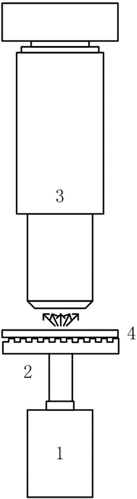
[0054] figure 1 It is a structural principle diagram of the microstructure-based frequency-shifting super-resolution microscopic imaging device of the present invention.

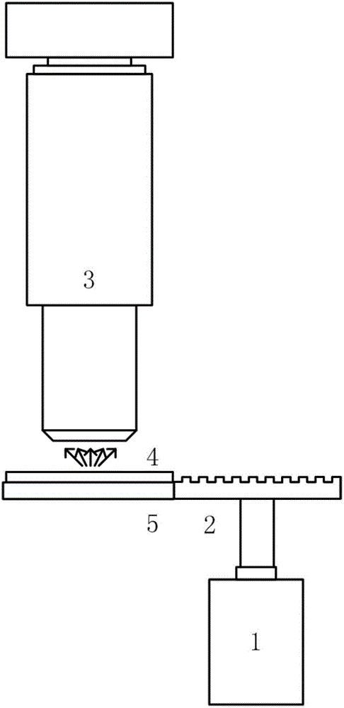
[0055] Such as figure 1 As shown, the microstructure-based frequency-shifting super-resolution microscopic imaging device includes: laser 1, microstructure 2, microscope 3, and sample 4.

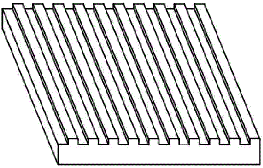
[0056] Laser 1, microstructure 2, microscope 3 and sample 4 are located on the coaxial optical path. The incident illumination light emitted from the laser 1 is vertically irradiated on the microstructure 2 . Wherein, the incident illumination light refers to visible monochromatic linearly polarized collimated light with the same polarization direction and a wavelength in the range of 380-780 nm. The microstructure 2 refers to a microstructure ...


PUM


Abstract

The invention discloses a frequency-shift super-resolution microscopic imaging method based on a microstructure. Surface waves are formed by emitting illumination light on the microstructure perpendicularly. The surface waves are used for illuminating the surface of a sample and intensity images are received from a far field through a microscope. A corresponding frequency spectrum is obtained through performing Fourier transform to the intensity images. The obtained frequency spectrum is restored by utilizing a frequency shift algorithm and corresponding frequency spectrum restoration images are obtained. The direction of the surface waves leaded into the sample is changed until a range from 0 to 360 degrees is covered. The above steps are repeated, so that frequency restoration images in different directions are obtained. The frequency restoration images in the different directions are overlapped, so that a complete high-frequency frequency spectrum image is obtained. Fourier inversion is applied to the complete high-frequency frequency spectrum image, so that a super-resolution microscopic image of the sample for observing is obtained. The invention also discloses a frequency-shift super-resolution microscopic imaging device based on the microstructure.

Description

technical field [0001] The invention belongs to the field of microscopic observation and measurement, and in particular relates to a microstructure-based frequency-shifting super-resolution microscopic imaging method and device. Background technique [0002] Nanotechnology and biotechnology are the fastest-growing and hottest scientific fields in the 21st century. Nanotechnology has a wide range of applications, including imaging, measurement, processing, manipulation, etc. within the scale of 1-100nm. Many important organisms such as glucose, antibodies, viruses, etc. are in this scale range, and the need to study these tiny objects has driven the development of high-resolution microscopy. In turn, the development of super-resolution microscopy has also promoted the progress of the entire life sciences. A major advantage of light microscopy over other microscopy techniques is the ability to study living cells in their natural state. [0003] Since the world's first optic...

Claims


Application Information

Patent Timeline
Patent Type & Authority Patents(China)
IPC IPC(8): G02B27/58G02B21/06
Inventor 刘旭郝翔匡翠方李海峰
Owner ZHEJIANG UNIV
Why Eureka
Try Eureka