
Frequency-shift super-resolution microimaging method and device based on evanescent field illumination
A technology of microscopic imaging and evanescent field, applied in measurement devices, analysis materials, material analysis by optical means, etc., can solve the problems of complex system structure, inability to use non-fluorescent samples, cumbersome sample processing, etc., and achieve high resolution. The effect of high precision, high image refresh rate and simple structure
- Summary
- Abstract
- Description
- Claims
- Application Information
AI Technical Summary
Problems solved by technology
Method used
Image

Examples
Embodiment 1
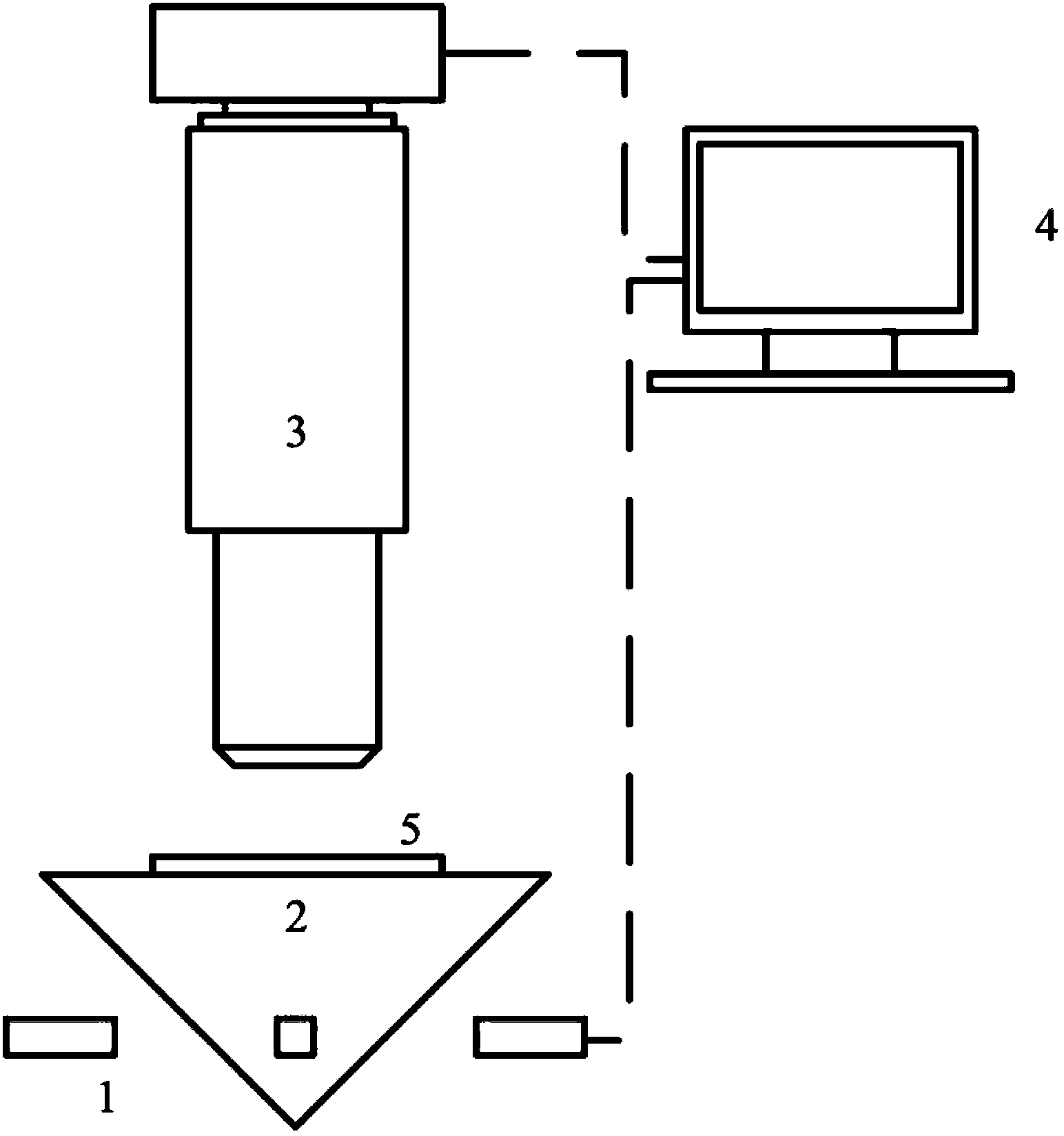
[0066] Such as figure 1 As shown, the device of the frequency-shifting super-resolution microscopic imaging system based on evanescent field illumination includes: a light source group 1, a prism 2, a microscope 3, a computer 4, and a sample 5.
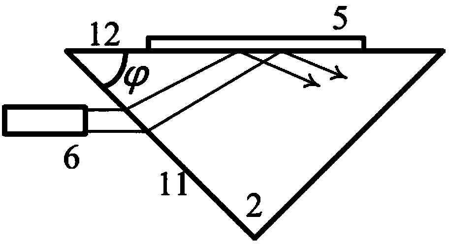
[0067] The light source group 1, the prism 2, the microscope 3 and the sample 5 are located on the coaxial optical path. The incident illumination light emitted by a single sub-light source 6 in the light source group 1 is totally reflected in the prism 2 to produce an evanescent field to illuminate the sample 5 . The generated light intensity distribution is collected and analyzed by the microscope 4 in the far field. Wherein, the incident illumination light refers to visible monochromatic linearly polarized collimated light with the same polarization direction and a wavelength in the range of 380-780 nm.
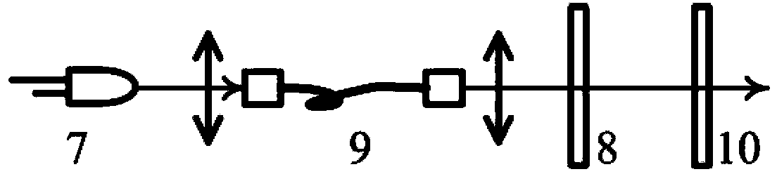
[0068] Fundamentally speaking, the incident illumination light is provided by LED7, in order to meet the requirements of the a...
Embodiment 2
[0086] Except in the specific embodiment of the present inventionfigure 1 In addition to the structural principle diagram provided in , the present invention can also improve the lighting method under the premise of ensuring the same principle.
[0087] Such as Figure 8 Shown is a structural principle diagram of the improved illumination mode of the frequency-shifting super-resolution microscopic imaging device based on evanescent field illumination of the present invention.
[0088] Such as Figure 8 As shown, after improving the illumination mode, the device of the frequency-shifting super-resolution microscopic imaging system based on evanescent field illumination includes: a laser light source 13, a vibrating mirror 14, a focusing mirror 15, a reflecting mirror 16, a total reflection objective lens 17, Slide 18, Microscope 3, Computer 4, Sample 5.
[0089] Laser light source 13, vibrating mirror 14, focusing mirror 15, reflecting mirror 16, total reflection objective le...
Embodiment 3
[0093] In addition to the method described in Embodiment 1 that can improve the illumination method, it can also be improved by using an off-center diaphragm.
[0094] Such as Figure 9 Shown is a schematic diagram of the structure of the evanescent field illumination-based frequency-shifting super-resolution microscopic imaging device of the present invention after using an eccentric diaphragm to improve the illumination mode.
[0095] Such as Figure 9 As shown, after improving the illumination mode, the device of the frequency-shifting super-resolution microscopic imaging system based on evanescent field illumination includes: a laser light source 13, an eccentric diaphragm 19, a total reflection objective lens 17, a glass slide 18, and a microscope 3, Computer 4, Sample 5.
[0096] Laser light source 13, eccentric diaphragm 19, total reflection objective lens 17, glass slide 18, microscope 3, and sample 5 are located on the coaxial optical path. The incident illuminatio...
PUM
| Property | Measurement | Unit |
|---|---|---|
| wavelength | aaaaa | aaaaa |
| refractive index | aaaaa | aaaaa |
Abstract
Description
Claims
Application Information