
Tuner isolation input socket

A tuner and socket technology, applied in the field of radio frequency input sockets, can solve the problems of complex assembly process, high precision, and low production efficiency, and achieve the effect of simple assembly process, good high-frequency performance, and simple structure

Inactive Publication Date: 2013-10-16
HANGZHOU CHEELE ELECTRONICS +1
View PDF7 Cites 7 Cited by
  • Summary
  • Abstract
  • Description
  • Claims
  • Application Information

AI Technical Summary

Problems solved by technology

[0005] The invention provides a tuner isolation input socket with low cost, good high-frequency performance, full shielding, and simple assembly process; it solves the structure of connecting the radio frequency input socket with the equipment existing in the prior art Complicated, complex assembly process, high precision required, low production efficiency, high cost technical problems

Method used


Image

  • Tuner isolation input socket
  • Tuner isolation input socket
  • Tuner isolation input socket

Examples


Embodiment 1

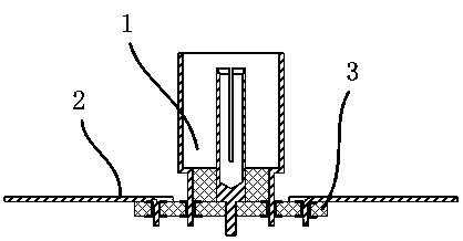
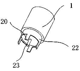
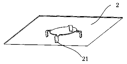
[0029] Such as figure 1 As shown, a tuner isolation input socket is applied to CAN tuners commonly used in TVs or set-top boxes. It includes a radio frequency input socket 1, and the radio frequency input socket 1 is connected to the pad on the circuit board 3 through the pin 20, and the shielding shell 2 is connected to the circuit board 3 at the same time. Such as figure 2 As shown, the radio frequency input socket 1 includes a cylindrical base 22, on which four radio frequency input socket pins 20 evenly distributed with the core pin 23 in the center are connected to the base 22, and the core pins 23 are inserted into the circuit board 3 Inside the through hole 24 in the center. Such as image 3 As shown, there is a circular through hole in the center of the shielding case 2 , and four shielding case pins 21 are evenly distributed under the shielding case 2 . The radio frequency input socket pin 20 and the shield shell pin 21 are welded in the through hole of the circu...

Embodiment 2

[0032] Such as Image 6 As shown, the difference from Embodiment 1 is that the outer ring pads 4, 5, 6, 7 and the inner ring pads 8, 9, 10, 11 are arranged staggered by 45°, and the rest are the same as in Embodiment 1.

Embodiment 3

[0034] Such as Figure 7 with 8 As shown, different from Embodiment 1, there are 6 pins 20 of the radio frequency input socket. Similarly, there are 6 pins 21 of the shielding shell, and the inner ring pads 8, 9, 10 on the circuit board are respectively , 11 and outer ring pads 4, 5, 6, 7, and component positions 14, 15, 16, 17 are all 6, and the corresponding coupling capacitors are also increased to 6. Using more pins for assembly will make the connection between the RF socket and the shielding shell closer to a fully enclosed coaxial link, which can obtain better high-frequency performance and shielding performance.


PUM


Abstract

The invention relates to an electronic component, and more specifically relates to a radio frequency input socket which can be used to block direct-current signals and low-frequency signals and make radio frequency signals pass through. The tuner isolation input socket is characterized in that the radio frequency input socket is fixed on a main circuit board, the ground plane of the radio frequency input socket and the ground plane of the main circuit board are provided with a capacitor therebetween; or the radio frequency input socket is fixed on a circuit board, the circuit board is provided with wire routing and a capacitor, a shielding case is fixed on the circuit board at the same time, and the ground plane of the radio frequency socket is connected with the shielding case through the wire routing and the capacitor on the circuit board. The tuner isolation input socket provided by the invention has the advantages of low cost, good high-frequency performance, complete shielding and simple assembly process, and solves the technical problem that an existing radio frequency input socket in the prior art is complex in structure and assembly process, high in required accuracy, low in production efficiency and high in cost.

Description

technical field [0001] The invention relates to electronic parts, more specifically, a radio frequency input socket with the function of blocking direct current and low frequency signals and passing radio frequency signals. Background technique [0002] The cable TV network connects the set-top boxes or TVs of every household through cables. There may be inconsistencies in ground potential between users and between users and cable TV transmission equipment, which will generate ground loop circulation in the cables, causing the cables to heat up. The equipment is damaged, which may cause a fire in severe cases. [0003] Use the RF signal ground loop isolator to cut off the ground loop current and prevent accidents. This type of isolator is usually implemented by two coaxial connectors and several capacitors, and the grounds of the two coaxial connectors are connected by capacitors. Hundreds to thousands of pF capacitors have low impedance to 48MHz-950MHz cable TV signals, b...

Claims


Application Information

Patent Timeline
Patent Type & Authority Applications(China)
IPC IPC(8): H01R24/50H01R24/42H01R13/73H01P1/20
Inventor 李君温志伟韩旭杉
Owner HANGZHOU CHEELE ELECTRONICS
Learn More