Guide wire for medical use
A medical and guide wire technology, applied in the field of medical guide wires, can solve the problems of poor indentation and bending rigidity (low kink resistance of the guide wire, etc.), and achieve good torque transmission, high bending rigidity, maintaining Excellent effect
- Summary
- Abstract
- Description
- Claims
- Application Information
AI Technical Summary
Problems solved by technology
Method used
Image

Examples
no. 1 approach >
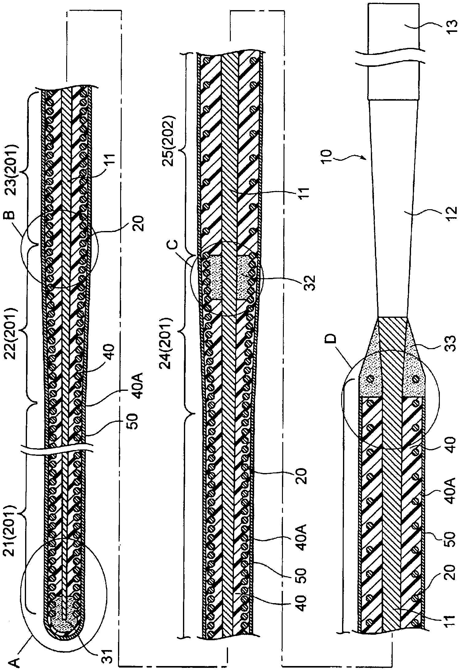
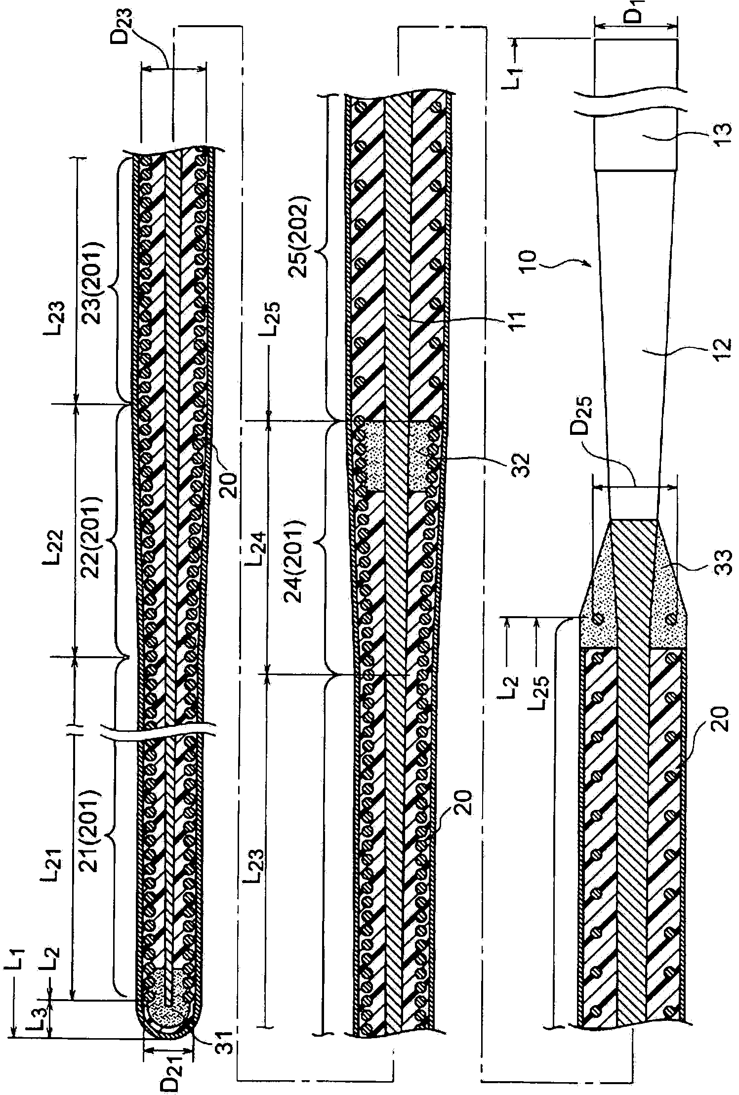
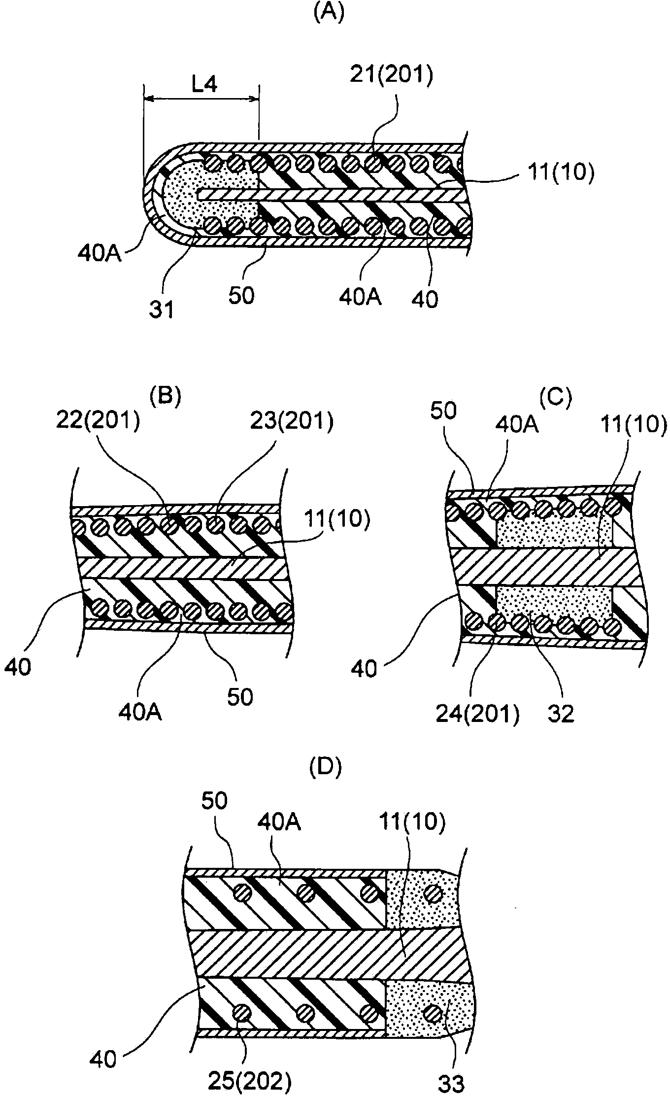
[0096] Figure 1 ~ Figure 3 The shown medical guide wire of this embodiment is a medical guide wire having a core wire 10 made of austenitic stainless steel with a tensile strength of 2600 to 3000 MPa and a coil spring 20, and It has a proximal end side large diameter portion 13 with an outer diameter of 0.012 inches or more, a distal end side small diameter portion 11 with an outer diameter smaller than the proximal end side large diameter portion 13, a proximal end side large diameter portion 13 and a distal end side large diameter portion 11. The tapered portion 12 between the small-diameter portions 11 on the end side, the coil spring 20 is composed of a coil that is axially installed on the outer circumference of the small-diameter portion 11 at the distal end side of the core wire 10 and has a coil diameter 1.1 to 2.0 times the coil wire diameter. The pitched densely wound portion 201 and the thickly wound portion 202 continuous with the densely wound portion 201 and hav...
no. 2 approach >
[0201] Figure 6 The guidewire shown has a core wire 10 and a coil spring 20B.
[0202] The core wire 10 has a small-diameter portion 11 on the distal end side tapered to increase in diameter in the proximal direction, a tapered portion 12 enlarged in the proximal direction, and a large-diameter portion 13 on the proximal end side.
[0203] The small-diameter portion 11 at the distal end, the tapered portion 12 and the large-diameter portion 13 at the proximal end are integrally formed of the same wire material (for example, a round rod member).
[0204] The cross-sections of the tapered portion 12 and the large-diameter portion 13 at the proximal end are substantially circular.
[0205] The proximal end side of the small-diameter portion 11 on the distal end side has a substantially circular cross-section, but the distal end side of the small-diameter portion 11 on the distal end side can also be formed into a plate shape by compressing a wire rod. In this case, the cross-se...
no. 3 approach >
[0270] Figure 9 The guidewire shown has a core wire 10 and a coil spring 20C.
[0271]The core wire 10 has a small-diameter portion 11 on the distal end side tapered to increase in diameter in the proximal direction, a tapered portion 12 enlarged in the proximal direction, and a large-diameter portion 13 on the proximal end side.
[0272] The small-diameter portion 11 at the distal end, the tapered portion 12 and the large-diameter portion 13 at the proximal end are integrally formed of the same wire material (for example, a round rod member).
[0273] The cross-sections of the tapered portion 12 and the large-diameter portion 13 at the proximal end are substantially circular.
[0274] The cross-section of the proximal end side of the small-diameter portion 11 on the distal end side is substantially circular, but the distal end side of the small-diameter portion 11 on the distal end side may also be in the form of a plate formed by compressing a wire rod. In this case, the c...
PUM
| Property | Measurement | Unit |
|---|---|---|
| tensile strength | aaaaa | aaaaa |
| length | aaaaa | aaaaa |
| length | aaaaa | aaaaa |
Abstract
Description
Claims
Application Information
 - R&D
- Intellectual Property
- Life Sciences
- Materials
- Tech Scout
- Unparalleled Data Quality
- Higher Quality Content
- 60% Fewer Hallucinations
Browse by: Latest US Patents, China's latest patents, Technical Efficacy Thesaurus, Application Domain, Technology Topic, Popular Technical Reports.
© 2025 PatSnap. All rights reserved.Legal|Privacy policy|Modern Slavery Act Transparency Statement|Sitemap|About US| Contact US: help@patsnap.com