Welding device

A welding device and control device technology, applied in auxiliary devices, welding equipment, welding equipment, etc., can solve problems such as taking a long time and hindering the efficiency of welding operations

Active Publication Date: 2013-10-23
KOBE STEEL LTD
View PDF8 Cites 22 Cited by
  • Summary
  • Abstract
  • Description
  • Claims
  • Application Information

AI Technical Summary

Problems solved by technology

[0008] However, since the welding device proposed in Patent Document 1 is reproduced based on information input from the teaching pendant, in order to cope with steel structures with various shapes and sizes, it is necessary to individually complete the corresponding to the various shapes and sizes. The teaching data and welding conditions of
That is, the welding device proposed in Patent Document 1 does not have a unit that can easily input information such as the size of the steel structure, and automatically completes the motion trajectory of the welding robot based on the information such as the size of the steel structure. As a unit with welding conditions, it takes a lot of time to prepare for starting welding work, which hinders the efficiency of welding work for welding parts that change one by one, such as steel skeleton structures.

Method used


Image

  • Welding device
  • Welding device
  • Welding device

Examples


no. 1 approach

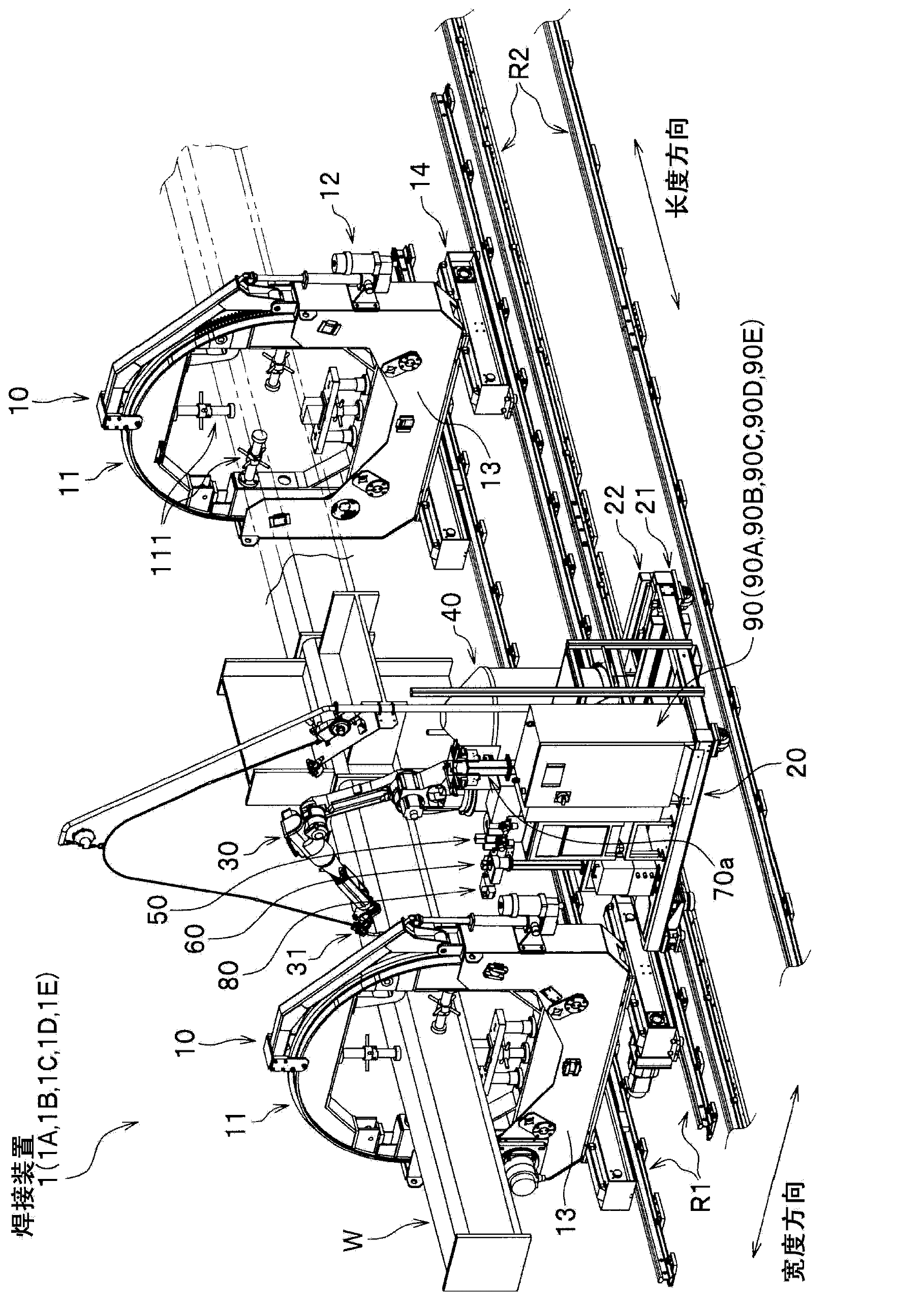
[0162] refer to Figure 1 to Figure 9 The welding device according to the first embodiment of the present invention will be described. The welding device 1 is a device for welding a steel frame structure as a workpiece for welding by, for example, gas shielded arc welding. Such as figure 1 As shown, the welding device 1 includes: a rotary positioner 10 , a trolley 20 , a welding robot 30 , a wire supply container 40 , a tip replacement device 50 , a tip cleaning device 60 , a wire cutting device 80 , and a welding control device 90 . In addition, the welding device 1 except figure 1 In addition to the shown structure, a welding slag removing device 70 is also provided (refer to Figure 6 ).

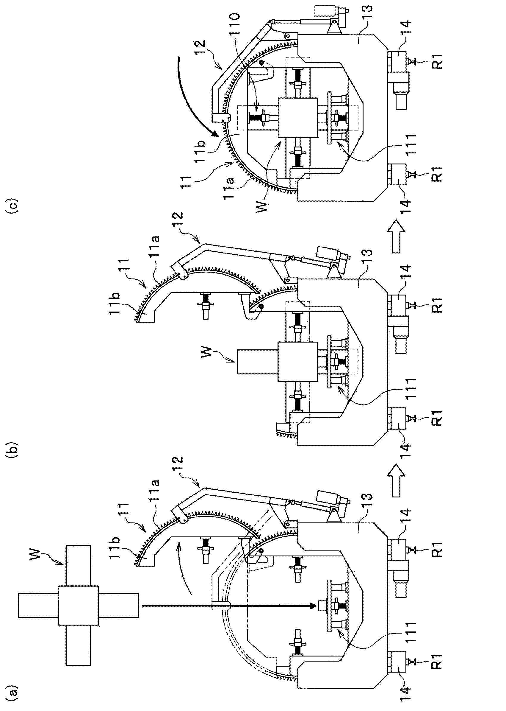
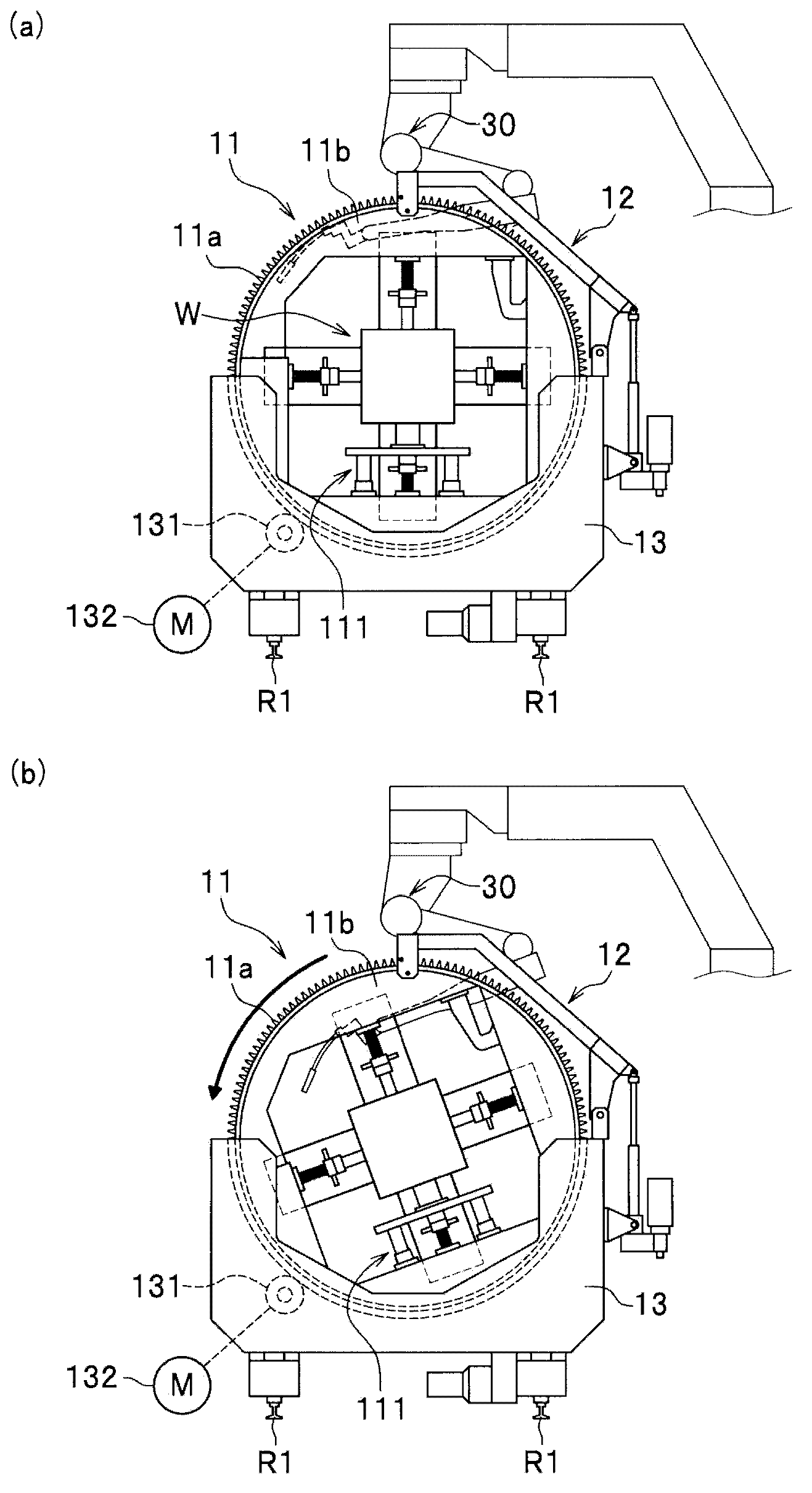
[0163] (rotary locator)

[0164] The rotation positioner 10 holds and rotates the steel structure W during welding. Such as figure 1As shown, the rotary positioner 10 is composed of a pair, and holds the columnar steel structure W at two points in the longitudinal direction of the ...

no. 2 approach

[0233] Below, refer to Figure 11 1A of welding apparatuses concerning 2nd Embodiment of this invention are demonstrated. Such as figure 1 and Figure 11 As shown, 1 A of welding apparatuses has the structure similar to the welding apparatus 1 which concerns on 1st Embodiment except having provided the welding control apparatus 90A instead of the welding control apparatus 90. Therefore, hereinafter, the description will focus on the differences from the welding device 1 , and the detailed description of the configuration overlapping with the welding device 1 and the processing procedure of the welding device 1A will be omitted.

[0234] The welding control device 90A is a device in which a function of correcting an operation program according to the eccentricity of the steel frame structure W is added to the welding control device 90 described above. Such as Figure 11 As shown, the welding control device 90A further includes a center position calculation unit 96, an eccen...

no. 3 approach

[0240] Below, refer to Figure 12 A welding device 1B according to a third embodiment of the present invention will be described. Such as figure 1 and Figure 12 As shown, the welding device 1B has the same configuration as the welding device 1 according to the first embodiment except that a welding control device 90B is provided instead of the welding control device 90 . Therefore, in the following, the description will focus on the differences from the welding device 1, and the detailed description of the configuration overlapping with the welding device 1 and the processing procedure of the welding device 1B will be omitted.

[0241] The welding control device 90B is a device in which a function of obtaining the radius of the fillet portion of the steel frame structure W through sensor detection is added to the welding control device 90 described above. Such as Figure 12 As shown, the welding control device 90B further includes a position correction unit 99 and a fille...


PUM

PropertyMeasurementUnit
diameteraaaaaaaaaa

Abstract

The invention provides a welding device which makes welding operation automate and makes welding operation high efficient. The welding device (1) is provided with a welding control device (90) which control operation of a welding robot (30), the welding robot (30) welds a steel structure (W) which is used as a welding workpiece. The welding control device (90) is provided with an input unit (91). Through input performed by an operator or CAD data input of the steel structure (W), any one of the dimension of the steel structure (W) and a shape of a welded joint or both of the dimension and the shape, and information of whether to execute welding or not are input into the input unit (91). The welding control device (90) automatically generates motion tracks of the welding robot and welding conditions when the welding robot performs welding, and performs welding according to preset welding robot tracks and welding conditions corresponding to any one of the dimension of the steel structure (W) and the shape of the welded joint or both of the dimension and the shape.

Description

technical field [0001] The invention relates to a welding device for welding a steel bone column structure. Background technique [0002] Conventionally, a technique as shown in Patent Document 1 has been proposed as a welding device for a steel column structure. That is, Patent Document 1 proposes a welding device that inputs a welding speed setting signal and movement trajectory data of a welding torch to a robot controller from a teaching pendant, and performs regeneration based on the signals and data. [0003] 【Prior technical literature】 [0004] 【Patent Literature】 [0005] [Patent Document 1] Specification of Chinese Patent Application Publication No. 200410012044.2 [0006] 【Summary of Invention】 [0007] 【Problems to be solved by the invention】 [0008] However, since the welding device proposed in Patent Document 1 is reproduced based on information input from the teaching pendant, in order to cope with steel structures with various shapes and sizes, it is ne...

Claims


Application Information

Patent Timeline
Patent Type & Authority Applications(China)
IPC IPC(8): B23K9/04B23K9/12B23K37/04B23K9/10
Inventor 松村浩史定广健次高田笃人横田顺弘凑达治井上芳英小池武
Owner KOBE STEEL LTD
Why Eureka
Try Eureka