Building roof construction process

A construction technique and architectural technology, which is applied in the direction of building roofs, roof coverings, roof ventilation, etc., and can solve problems such as irregularities, poor exhaust effects, and easy blockage of exhaust holes

Inactive Publication Date: 2013-10-23
陕西建工集团有限公司 +1
View PDF8 Cites 10 Cited by
  • Summary
  • Abstract
  • Description
  • Claims
  • Application Information

AI Technical Summary

Problems solved by technology

In the actual use process, there are many practical problems such as easy blockage, easy damage, poor exhaust, and poor exhaust effect in the above-mentioned vent holes.
Nowadays, in the actual construction of building roofs, there is no uniform and standardized construction method to follow in the construction of the roof exhaust system, the construction of the grid joints and caulking on the rigid protective layer, so there are inevitably construction operations in the actual construction. Many problems, such as randomness, non-standardization, low work efficiency, and difficult guarantee of construction quality, not only affect the construction period, but also have a great impact on the construction quality of the formed building roof.

Method used


Image

  • Building roof construction process
  • Building roof construction process
  • Building roof construction process

Examples


Embodiment 1

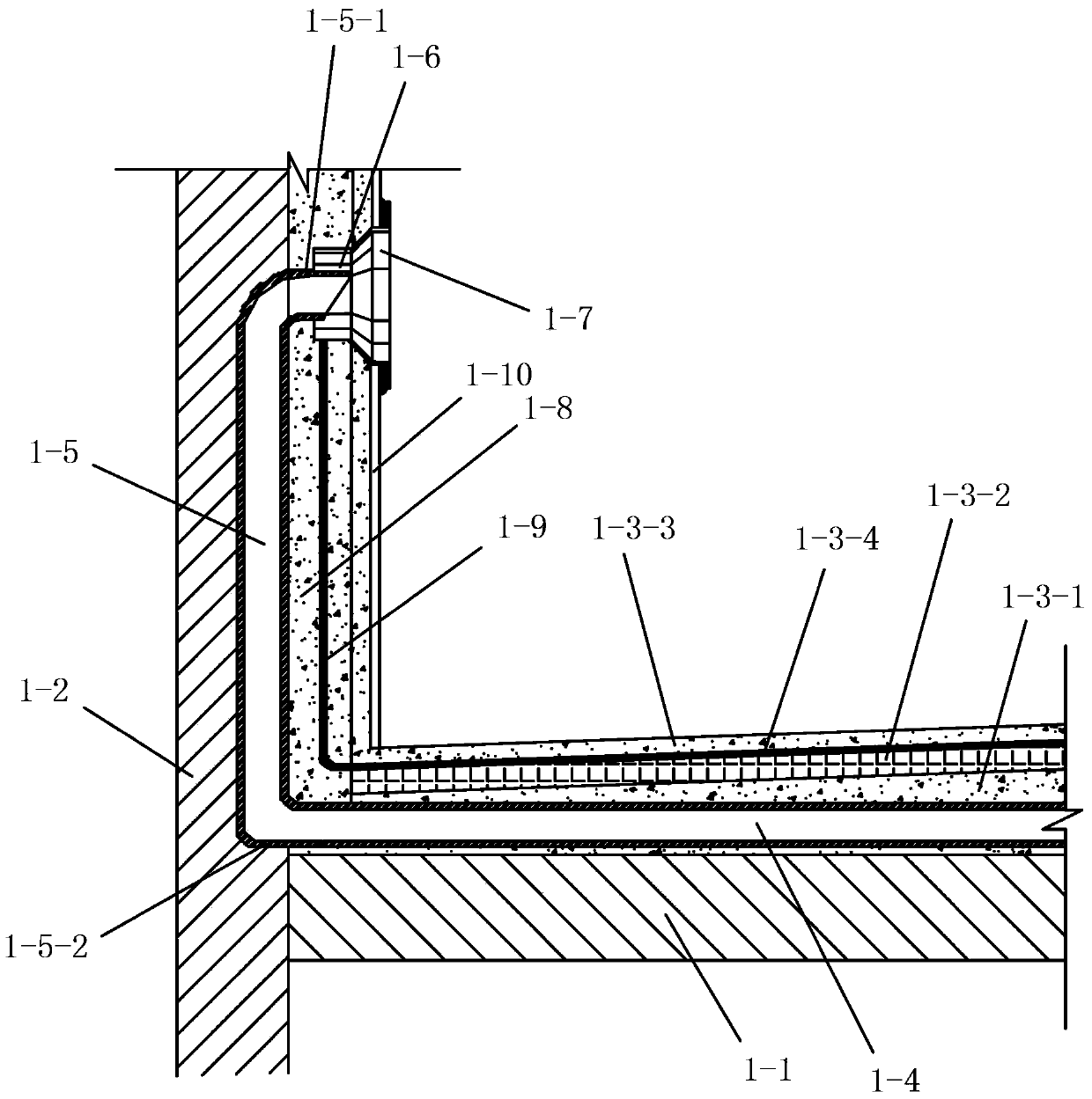
[0066] Such as Figure 1-2 , Figure 1-3 As shown, in this embodiment, the constructed roof includes a roof structural panel 1-1, a parapet 1-2 arranged on the sides of the roof structural panel 1-1, and a roof surface layer laid on the roof structural panel 1-1. . The roof surface layer includes a slope-finding layer 1-3-1 laid on the roof structural board 1-1, a heat-insulating layer 1-3-2 laid on the slope-making layer 1-3-1, and a heat-preserving layer laid on the The roof waterproof layer 1-3-4 on the 1-3-2 and the rigid protective layer 1-3-3 paved on the roof waterproof layer 1-3-4. A roof exhaust system is provided on the constructed roof, and the roof exhaust system includes multiple first horizontal exhaust pipes 1-4 laid in the slope-making layer 1-3-1 or the insulation layer 1-3-2 . Both ends of each first horizontal exhaust pipe 1-4 are connected to a vertical exhaust pipe 1-5, and the first horizontal exhaust pipe 1-4 and the vertical exhaust pipe 1- 5 are P...

Embodiment 2

[0147] In this embodiment, the difference from Embodiment 1 is that the plurality of second exhaust pipes are arranged obliquely, and the inclination angle of each second exhaust pipe is the same as the roof of the construction roof at the location where it is arranged. The slope is consistent. The plurality of first horizontal exhaust pipes 1-4 are arranged parallel to the ridge line of the constructed roof, and the plurality of first horizontal exhaust pipes 1-4 include one arranged on the ridge line of the constructed roof. The first horizontal exhaust pipe in the middle part and multiple channels are respectively arranged on the left side of the first horizontal exhaust pipe in the middle part; The first horizontal exhaust pipe on the right side, among the multiple first horizontal exhaust pipes 1-4, the layout position of the middle first horizontal exhaust pipe is the highest. The plurality of second exhaust pipes includes a plurality of left second exhaust pipes respec...

Embodiment 3

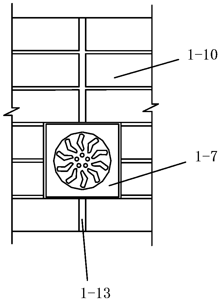
[0154] Such as image 3 As shown, in this embodiment, the difference from Embodiment 1 is that: when constructing the parapet wall 1-2 in step 2, a concrete boss 3 needs to be set on the inner wall surface of the parapet wall 1-2 -2, the concrete boss 3-2 is poured together with the parapet 1-2, and the concrete boss 3-2 is the flooded eaves of the parapet 1-2; the concrete boss 3-2 is Horizontal layout; after the exhaust pipe connection in step 4 is completed, it is necessary to evenly paint a layer of plastering layer 1-8 on the inner wall of the parapet wall 1-2 completed in step 2, and the plastering layer Parapet facing bricks 1-10 are pasted on the first 1-8; the plastering layer 1-8 is divided into upper and lower parts with the concrete boss 3-2 as the boundary, wherein the plastering layer 1-8 is located above the concrete boss 3-2 The plastering layer one 1-8 is cement mortar layer five 3-3-5, and the parapet facing brick 1-10 paved on the cement mortar layer five 3...


PUM


Abstract

The invention discloses a building roof construction process. A construction roof comprises a roof structure plate, a parapet wall and a roof surface layer, wherein the parapet wall is arranged above the roof structure plate, the roof surface layer is paved on the roof structure plate, a roof exhaust system is arranged on the construction roof and comprises a plurality of first horizontal exhaust pipes, the first horizontal exhaust pipes are respectively laid in a slope finding layer or a heat insulation layer in the roof surface layer, two ends of each first horizontal exhaust pipe are respectively connected with a vertical exhaust pipe, and the vertical exhaust pipes are embedded in the side walls of the parapet wall and a discharge flue or the side wall of an exhaust passage. The construction process of a construction roof comprises the steps of 1, surveying and setting out; 2, parapet wall, discharge flue and exhaust passage construction; 3, horizontal exhaust pipe positioning installation; 4, exhaust pipe connection; 5, roof surface layer construction; and 6, rigid protecting layer mesh division and caulking construction. The construction process has the advantages that the steps are simple, the operability is high, the realization is convenient, in addition, the work efficiency is high, the construction effect is good, and the construction quality of the construction forming building roof can be effectively ensured.

Description

technical field [0001] The invention belongs to the technical field of building roof construction, and in particular relates to a building roof construction technology. Background technique [0002] The building roof surface layer refers to the part above the roof structure panel, including the roof slope layer, insulation layer, waterproof layer, rigid protective layer and finishing layer. In order to reduce cracks, the split joints are pre-set on the roof slope layer, rigid waterproof layer and rigid protective layer. The rigid protective layer is only made into V-shaped grooves on the surface, which is called surface split joints. Setting a certain number of grid joints can reduce the area of ​​a single concrete layer, thereby reducing its deformation due to expansion and warping, and can effectively prevent and limit the generation of cracks. The parapet refers to the low wall around the roof of the building. In addition to maintaining safety, the main function is to ap...

Claims


Application Information

Patent Timeline
Patent Type & Authority Applications(China)
IPC IPC(8): E04D11/02E04D13/17
Inventor 王巧利王西胜薛东智
Owner 陕西建工集团有限公司
Why Eureka
Try Eureka