Mine compressed air self-negative-pressure orifice dust removing device

A dust-removing device and self-conceited technology, which are used in flushing wellbore, wellbore/well components, earth-moving drilling, etc., can solve the problems of inconvenient installation and use, poor dust removal effect, complex structure, etc., and achieve simple structure and reduce inhalation. The effect of high dust collection ability and strong dust collection ability

Inactive Publication Date: 2013-10-23
JIAOZUO CHANGHAI MACHINERY TECH
View PDF6 Cites 5 Cited by
  • Summary
  • Abstract
  • Description
  • Claims
  • Application Information

AI Technical Summary

Problems solved by technology

[0003] The purpose of the present invention is to overcome the existing problems of complex structure, inconvenient installation and use, poor dust removal effect and potential safety hazards caused by the use of electric negative pressure fans as exhaust components of the existing mine drilling head dust removal device, and to provide a simple structure, installation Easy to use, good dust removal effect, using the mine's original compressed air system to provide compressed air to generate negative pressure, no safety hazard mine compressed air self-negative pressure orifice dust removal device

Method used


Image

  • Mine compressed air self-negative-pressure orifice dust removing device
  • Mine compressed air self-negative-pressure orifice dust removing device

Examples


Embodiment 1

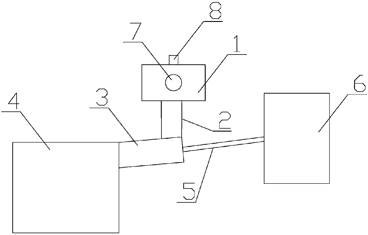
[0022] Embodiment 1: as figure 1 As shown, a mine pressure air self-negative pressure orifice dust removal device includes a square dust collection chamber 1, a drill pipe penetration hole 7 is opened in the front middle of the dust collection chamber 1, there is no cavity wall on the back, and a top surface is provided with a The inlet of the extraction pipeline 8 has a connecting port on the bottom surface, which is connected to the upper opening of the cylindrical dust suction chamber 2 through the connection port. On the connection port, one end of the dust-reducing pipeline 3 is connected to the dust-removing component 4. After the other end is closed, a through hole is provided at the center of the closed end surface, and the high-pressure air pipe 5 is connected to the dust-reducing pipeline 3 through the through hole. The high-pressure air pipe The other end of 5 connects mine pressure air system 6.

[0023] In specific use, the opening of the dust collection chamber ...

Embodiment 2

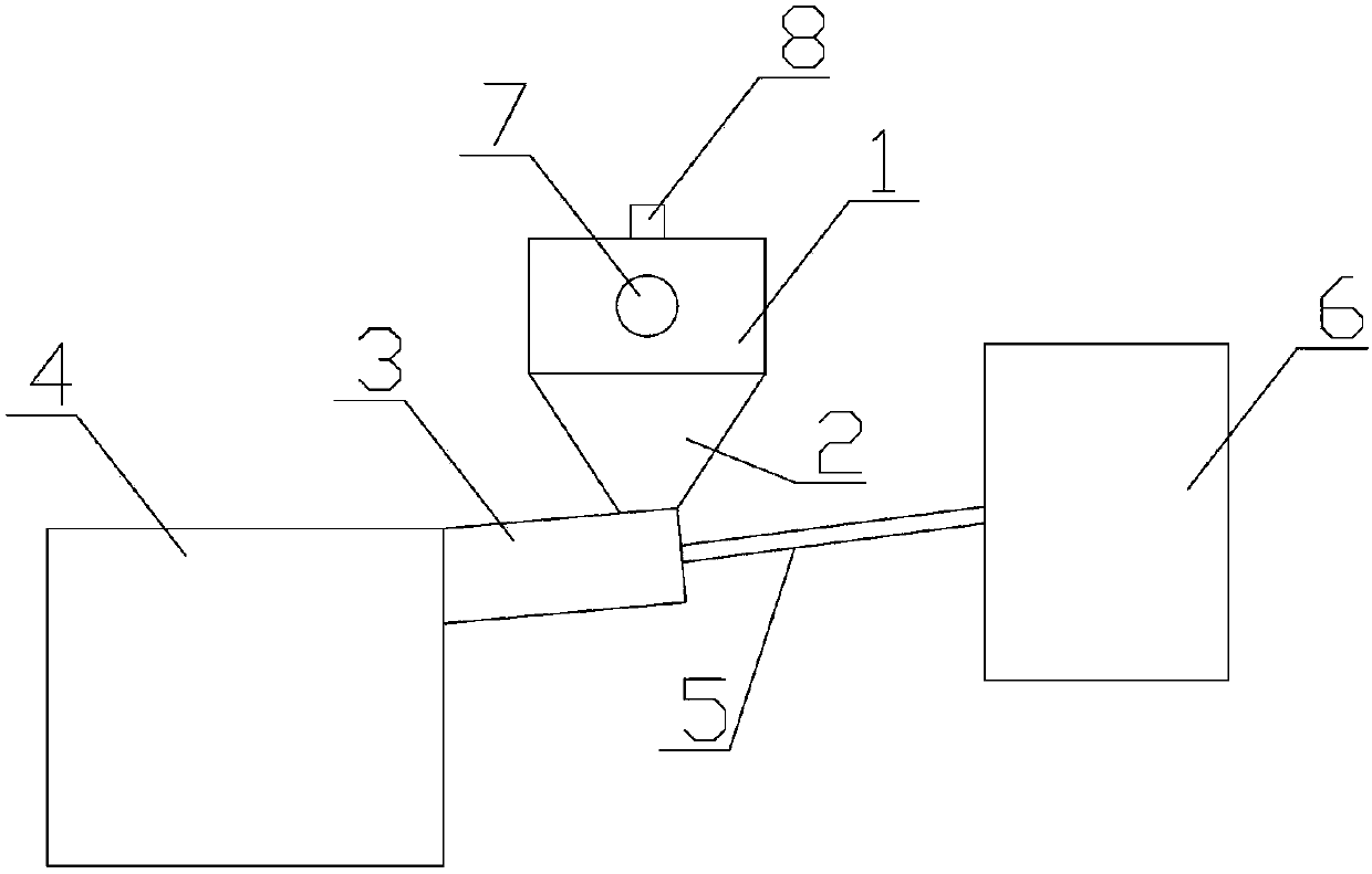
[0024] Embodiment 2: as figure 2 As shown, the difference from Example 1 is that the connection opening on the bottom surface of the dust collection chamber 1 accounts for the entire area of ​​the bottom surface of the dust collection chamber 1, that is, the bottom surface of the dust collection chamber 1 has no cavity wall, and the dust collection chamber 2 is A funnel-shaped cavity with closed surroundings. The larger opening above the dust collection chamber 2 has the same area as the bottom surface of the dust collection chamber 1. It is installed on the frame of the bottom surface of the dust collection chamber 1. The smaller opening below the dust collection chamber 2 is fixed and installed on the dust collection chamber. On the top surface of the pipeline 3, other components and connection methods are the same as those in Embodiment 1, and will not be described again.

[0025] As can be seen from the above specific implementation methods, compared with the prior art, t...


PUM


Abstract

The invention relates to a dust removing device, in particular to a mine compressed air self-negative-pressure orifice dust removing device, which can remove the produced dust during coal seam gas drainage drilling and gas emission drilling. The dust removing device comprises a dust collection cavity, a dust absorption cavity, a dust fall pipeline and a dust removing component, wherein the dust absorption cavity is arranged below the dust collection cavity; the dust fall pipeline is arranged below the dust absorption cavity; the dust removing component is connected to the tail end of the dust fall pipeline; the dust fall pipeline is connected with a high-pressure air pipe; the tail end of the high-pressure air pipe is connected with a mine compressed air system; mine compressed air enters the dust fall pipeline with static pressure water through the high-pressure air pipe; since the air velocity of the compressed air is high, the static pressure water is fully atomized; but when the compressed air is blown to the dust removing component through the dust fall pipeline, negative pressure is formed in the upper space of the dust fall pipeline and in the dust absorption cavity, so that all the dust collected in the dust collection cavity is fully absorbed into the dust removing component; and the dust removing device has the advantages of simple structure, convenience in mounting and use, good dust removing effect and no potential safety hazard.

Description

technical field [0001] The invention relates to a dust removal device, in particular to a mine pressure air self-negative pressure orifice dust removal device capable of removing dust generated during coal seam gas drainage boreholes and gas discharge boreholes. Background technique [0002] In the process of coal mining, especially during drilling construction, a large amount of floating coal powder particles will be produced, resulting in flying dust and low visibility at the construction site, which will bring safety hazards to coal mine production; in addition, a large number of coal powder particles are easily deposited on the drilling rig components Aggregation will increase the failure rate of drilling rig equipment, reduce the service life and safety; at the same time, coal powder particles and fine dust are suspended in the air, which can easily be inhaled into the lungs, causing great harm to the health of on-site workers . Most of the existing mine drilling head...

Claims


Application Information

Patent Timeline
Patent Type & Authority Applications(China)
IPC IPC(8): E21B21/015E21B21/14
Inventor 宋东峰彭燕赵长旗史文超
Owner JIAOZUO CHANGHAI MACHINERY TECH
Why Eureka
Try Eureka