Eureka AIR delivers breakthrough ideas for toughest innovation challenges, trusted by R&D personnel around the world.

Hole panoramic image pair three-dimensional imaging method

A stereoscopic imaging and panorama technology, applied in the direction of optics, instruments, optical components, etc., to achieve the effects of correct formula derivation, rigorous conception, and ingenious design

Active Publication Date: 2013-10-23
INST OF ROCK & SOIL MECHANICS CHINESE ACAD OF SCI
View PDF4 Cites 15 Cited by
  • Summary
  • Abstract
  • Description
  • Claims
  • Application Information

AI Technical Summary

Problems solved by technology

However, there are still some problems in the borehole imaging technology in both analog and digital methods: 1) The limitations of the basic assumptions
There is no need for the basic assumption of the cylindrical surface hole wall. Although the aperture data is required, it is only used for reference and comparison; 2) The imaging and positioning methods are simple

Method used


Image

  • Hole panoramic image pair three-dimensional imaging method
  • Hole panoramic image pair three-dimensional imaging method
  • Hole panoramic image pair three-dimensional imaging method

Examples


Embodiment 1

[0113] Embodiment 1: step 1, comprehensive selection

[0114] Geological drilling is the preferred target, and its diameter varies widely, so an appropriate range needs to be selected. Here, the most commonly used aperture range, ie 76mm-150mm, can be considered.

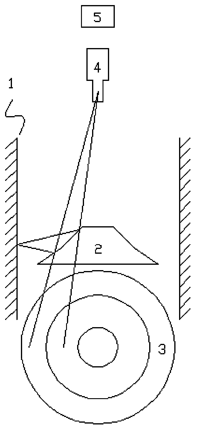
[0115] In order to achieve the purpose of panorama and three-dimensional imaging survey in the hole, imaging technology, optical transformation device technology and positioning method are necessary. However, considering the complexity of dual imaging components to achieve image pair imaging in the hole, the combination of imaging device and biconical mirror optical conversion device technology, wheel rolling measurement and electronic compass positioning method was selected.

[0116] Step 2. Technical Analysis

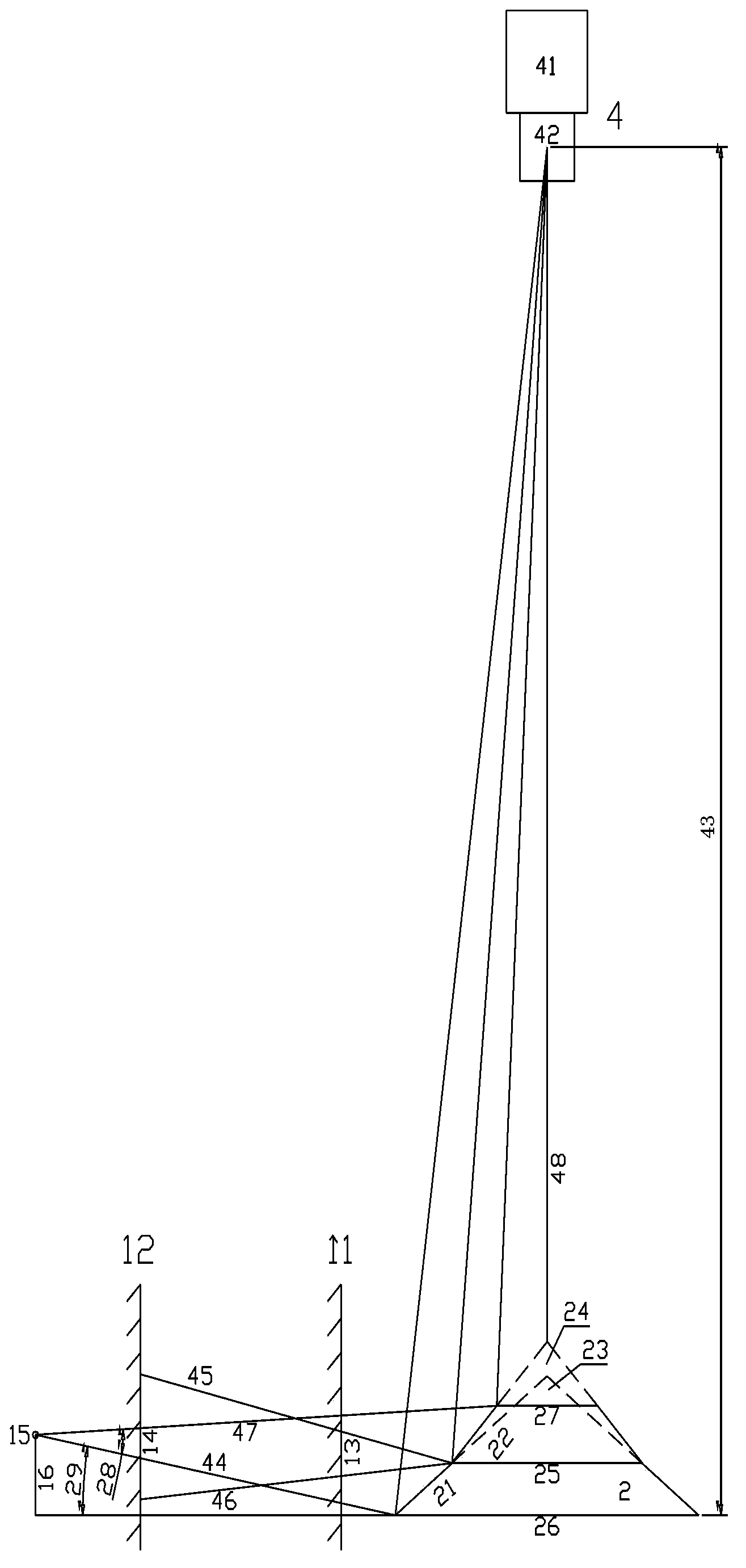
[0117] according to figure 2As shown, the imaging device 41 may use a CCD (Charge Coupled Device) imaging component, and the lens 42 is a fixed-focus lens with a focal length of f and a longitudinal fie...


PUM


Abstract

The invention discloses a hole panoramic image pair three-dimensional imaging method, which comprises a basic principle, a method, an optimized design and algorithm realization. According to the basic principle of the three-dimensional imaging, an imaging method for a 360-DEG drilling hole wall panoramic image-paired image containing the location information of an imaging device is provided by utilizing the technological combination of an optical converter of a twin-conical-surface lens, the imaging device and the space location; a calculation formula of a panoramic image-paired image is derived by theoretically analyzing the hole panoramic image pair imaging principle, the optimized analysis is carried out for the parameters of relevant technology and the layout design, and the corresponding software algorithm is established; and by analyzing a key point and difficulties for realizing the algorithm, the corresponding implementation scheme and flow block diagram are compiled. By adopting the hole panoramic image pair three-dimensional imaging method, the difficult problem of panoramic and three-dimensional detection inside the hole can be solved, a scientific method is provided for the precise detection inside the hole, the breakthrough and substantive progress of the drilling photograph technology can be realized, and the remarkable scientific significance and economical practicability can be realized.

Description

technical field [0001] The present invention relates to a stereoscopic imaging method of a panoramic image pair in a hole, and more particularly relates to a method for forming a panoramic image pair image of the hole wall by using a biconical mirror, and an imaging device to realize imaging of the image pair image and a stereoscopic image pair image for the wall of a borehole. The solution method; it breaks through the technical problem that the previous borehole imaging cannot realize three-dimensional imaging in the borehole, promotes the further development of borehole imaging technology, and is more suitable for fine in-hole detection. Background technique [0002] As the rock mass suffers from various tectonic movements and shallow geological transformation, there are various types of structural planes with different scales, different occurrences, and different properties in the rock mass. The spatial distribution and occurrence status of these structural planes It con...

Claims


Application Information

Patent Timeline
Patent Type & Authority Applications(China)
IPC IPC(8): E21B47/002G02B27/22
Inventor 王川婴韩增强胡胜
Owner INST OF ROCK & SOIL MECHANICS CHINESE ACAD OF SCI
Why Eureka
Eureka Blog
Learn More