

Heat insulating box, and refrigerator and hot-water storage device each comprising heat insulating box
A box, vacuum insulation technology, which is applied to household refrigeration devices, isolation of refrigeration devices, and protection of pipelines through thermal insulation, etc. The effect of sufficient thermal insulation
- Summary
- Abstract
- Description
- Claims
- Application Information
AI Technical Summary
Problems solved by technology
Method used
Image

Examples
Embodiment approach 1
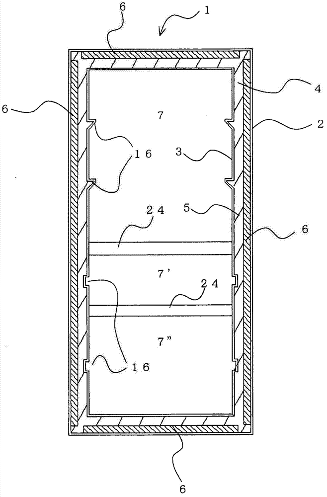
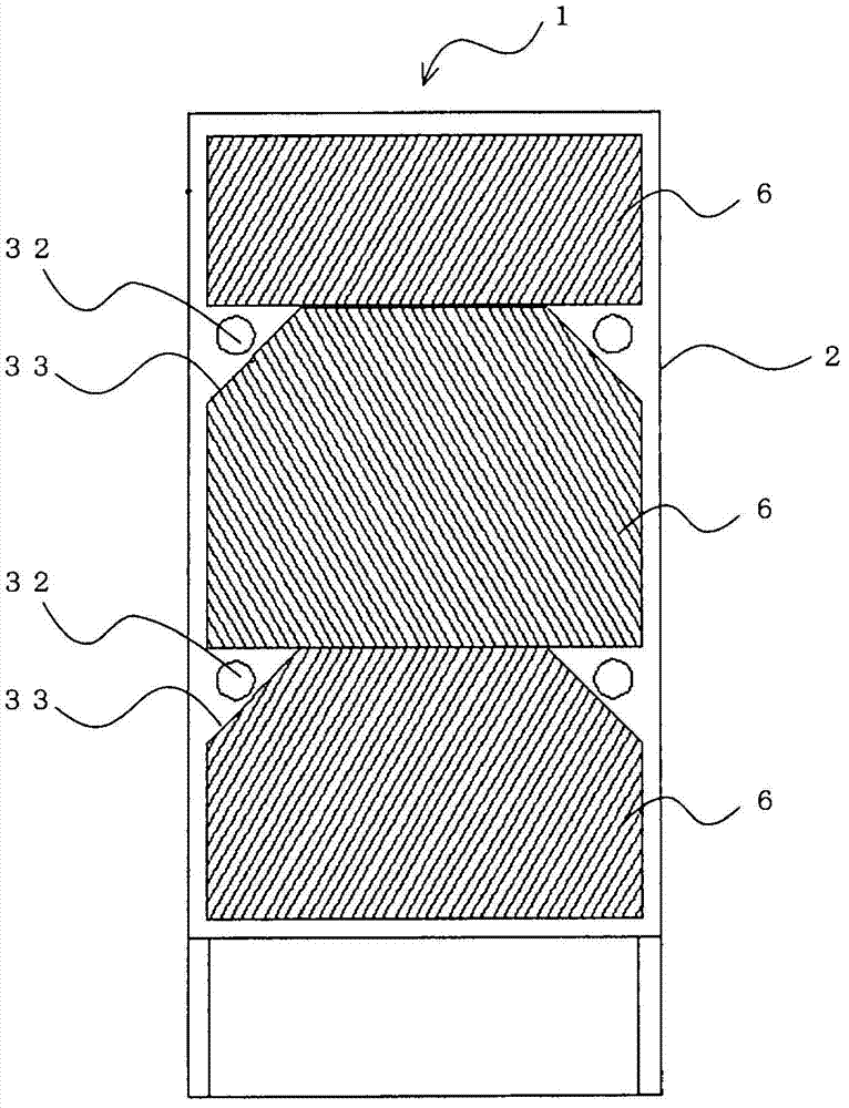
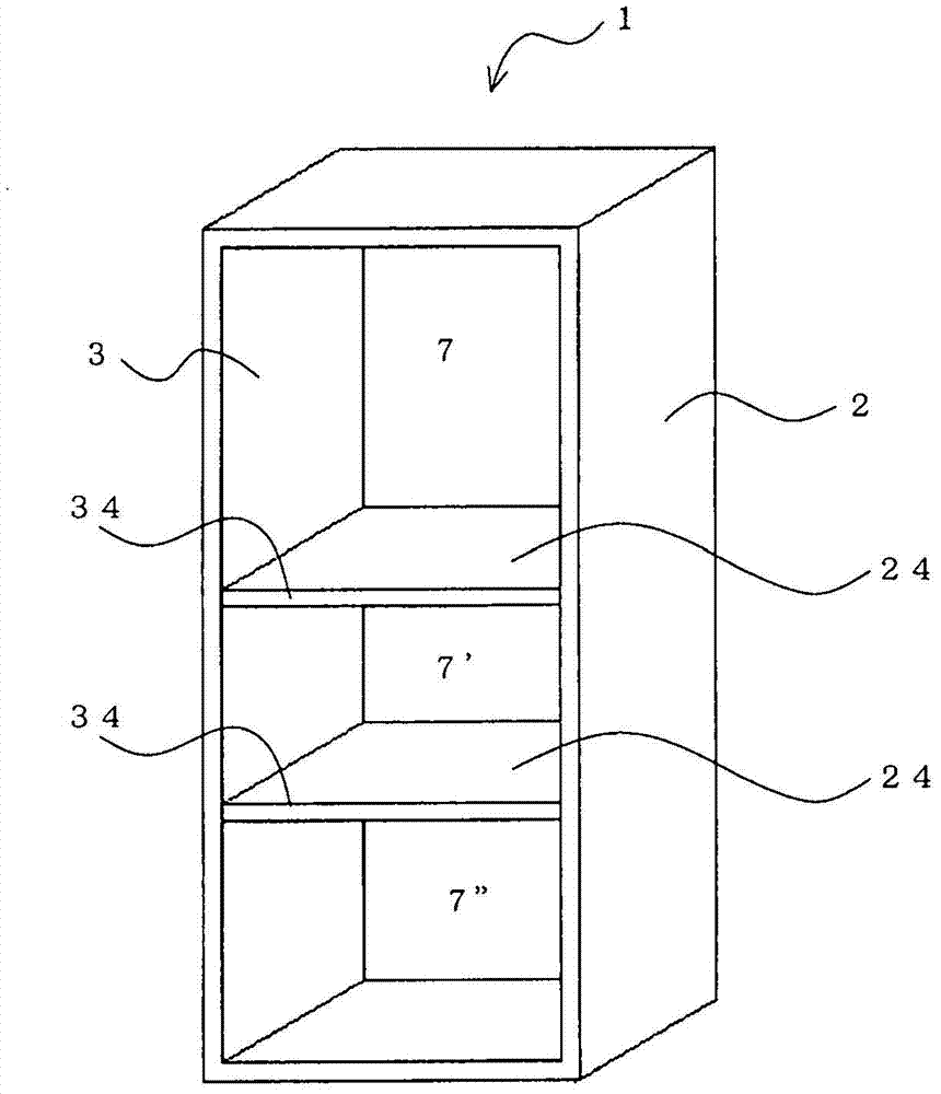
[0036] figure 1 It is a front cross-sectional view of the heat insulating box according to Embodiment 1 of the present invention. figure 2 is the rear view of the heat insulation box. in addition, image 3 is a perspective view of the heat insulation box. In addition, the vacuum heat insulating material 6 is actually arrange|positioned in the space 4 (corresponding to the 1st space of this invention) formed between the outer case 2 and the inner case 3 as follows. But when figure 2 In the figure, in order to easily understand the shape of the vacuum heat insulating material 6 arranged on the back side of the heat insulating box 1, the vacuum heat insulating material 6 is shown through the back surface of the outer box 2 (that is, the vacuum is indicated by a solid line). Insulation 6). In addition, in image 3 In , illustration of the guide rail 16 is omitted.
[0037] Hereinafter, the heat insulation box 1 of this Embodiment 1 is demonstrated using these drawings.
...
Embodiment approach 2
[0063] In Embodiment 1, the vacuum heat insulating material 6 is arrange|positioned in the space 4 formed between the outer case 2 and the inner case 3 by affixing the vacuum heat insulating material 6 to the outer case 2. Not limited to this, the vacuum heat insulating material 6 may be arrange|positioned in the space 4, for example as follows. Note that items that are not particularly described in Embodiment 2 are the same as in Embodiment 1, and the same functions and configurations will be described using the same reference numerals.
[0064] Figure 7 It is a front cross-sectional view of a heat insulation box according to Embodiment 2 of the present invention.
[0065] Such as Figure 7 As shown, in the heat insulation box 1 of the second embodiment, the condensation pipe 9 is provided on the inner surface side of the outer box 2 . The condenser pipe 9 is a refrigerant pipe through which high-temperature and high-pressure refrigerant discharged from the compressor flo...
Embodiment approach 3
[0071] Depending on the shape of the inner box 3 and the like, the vacuum heat insulating material 6 may be arranged in the space 4 as follows, for example, without being limited to the structures shown in Embodiment 1 and Embodiment 2. Note that items not particularly described in Embodiment 3 are the same as those in Embodiment 1 or Embodiment 2, and the same functions and configurations will be described using the same reference numerals.
[0072] Figure 8 It is a front sectional view showing the heat insulation box of Embodiment 3 of this invention.
[0073] Such as Figure 8 As shown, the heat insulation box 1 of the present embodiment 3 does not form the guide rail 16 in the inner box 3 (refer to figure 1 , Figure 7 )Structure. In this way, when the inner box 3 has a shape in which the vacuum heat insulating material 6 is easily attached, all or a part of the vacuum heat insulating material 6 may be arranged in the inner box 3 .
[0074] As mentioned above, in the...
PUM
| Property | Measurement | Unit |
|---|---|---|
| Flexural modulus of elasticity | aaaaa | aaaaa |
| Thermal conductivity | aaaaa | aaaaa |
| Thermal conductivity | aaaaa | aaaaa |
Abstract
Description
Claims
Application Information