
Heat transfer tubes and a heat exchanger using the same

A technology of heat transfer tubes and heat transfer components, which is applied in the field of heat exchangers and heat transfer tubes. It can solve the problems of inability to use pressure-resistant small-diameter tubes, difficulty in compaction, and increased pressure loss. The heat transfer efficiency will not Effects of reduction, constant cross-sectional area of ​​flow path, and improvement of thermal conductivity

Inactive Publication Date: 2013-10-23
CI KASEI COMPANY +1
View PDF6 Cites 7 Cited by
  • Summary
  • Abstract
  • Description
  • Claims
  • Application Information

AI Technical Summary

Problems solved by technology

Therefore, in order to be embedded in a device, it must be bent or coiled to form a predetermined external shape, making it difficult to compact
In addition, as the overall length increases, the pressure loss of the fluid (refrigerant, water) also increases, so it is necessary to use a large-diameter pipe body, and it is impossible to use a small-diameter pipe that is excellent in pressure resistance for high-pressure refrigerants.

Method used


Image

  • Heat transfer tubes and a heat exchanger using the same
  • Heat transfer tubes and a heat exchanger using the same
  • Heat transfer tubes and a heat exchanger using the same

Examples


Embodiment Construction

[0141] First, a first embodiment of the present invention will be described with reference to the drawings.

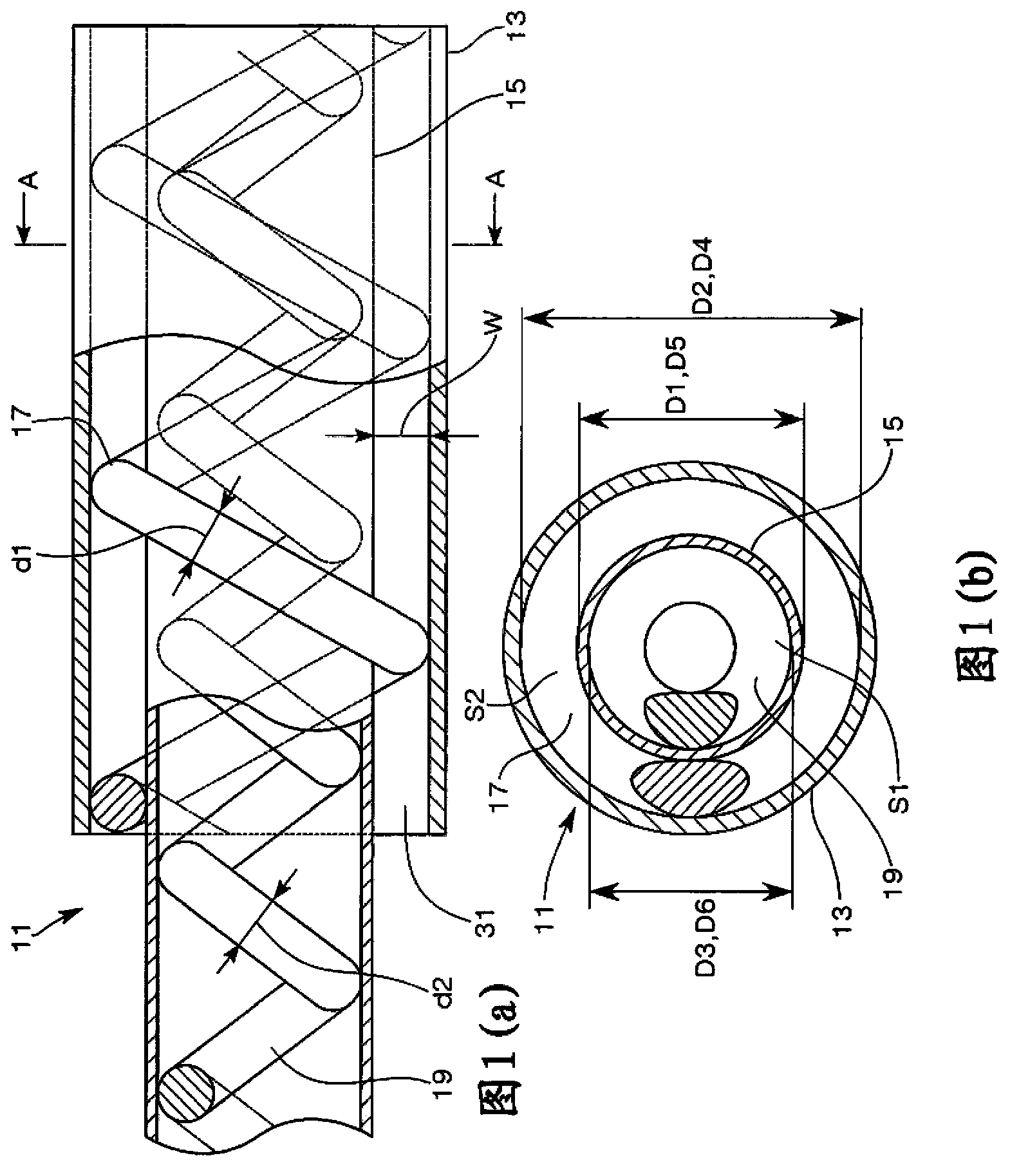
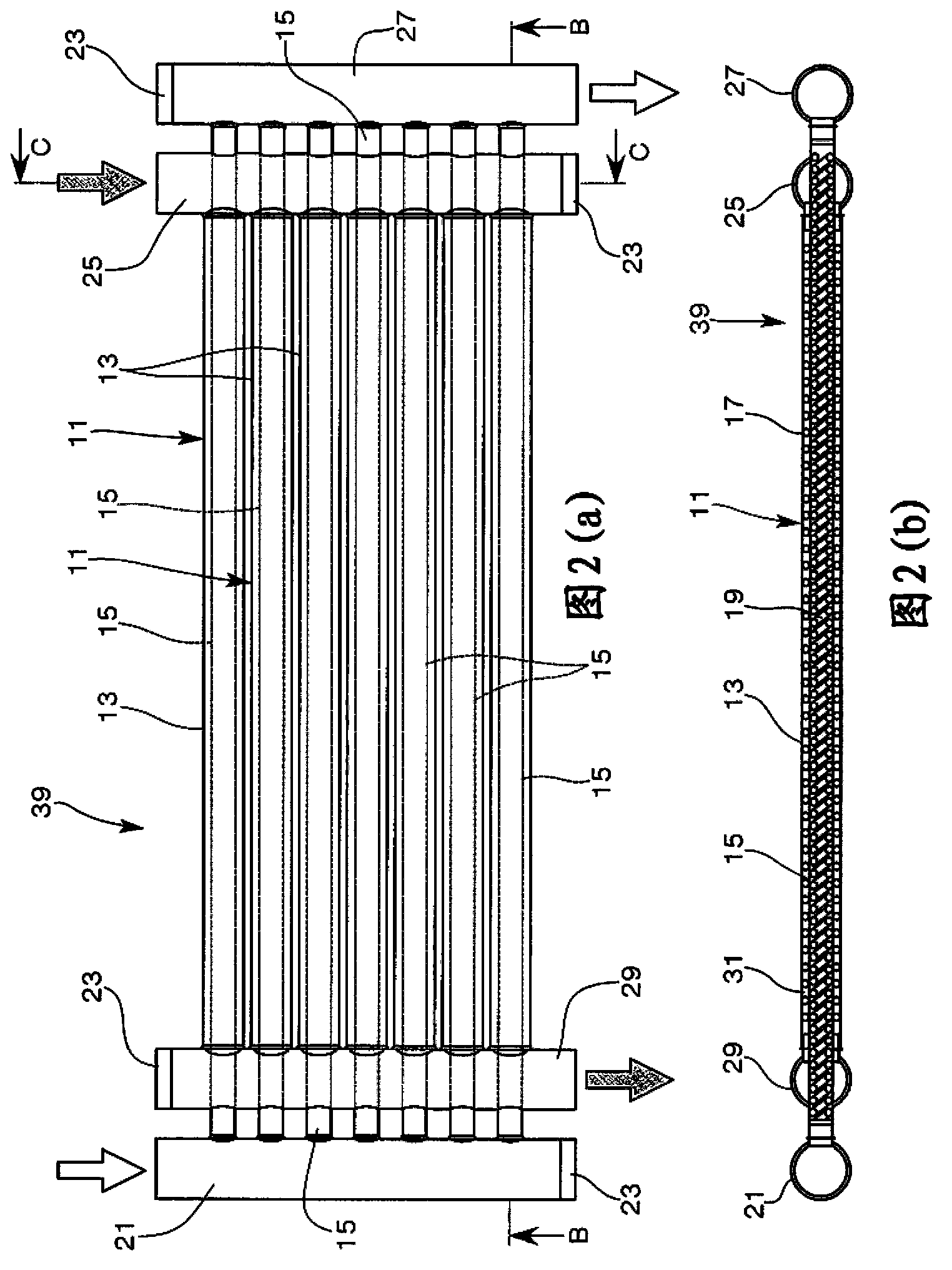
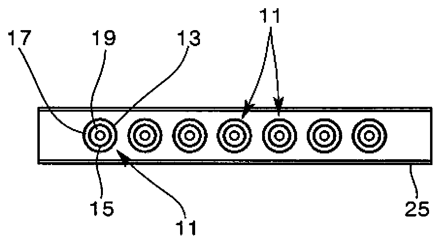
[0142] Fig. 1 (a) is a schematic enlarged sectional view showing the heat transfer tube of the present invention, Fig. 1 (b) is a diagram showing the A-A sectional view of Fig. 1 (a), and Fig. The plan view of the heat transfer tube column unit of the heat exchanger of the heat pipe, Fig. 2 (b) is the figure that represents the B-B line sectional view of this plan view, image 3 It is the C-C side sectional view of the heat transfer tube row unit shown in Fig. 2 (a), Fig. 2 (b), Figure 4 It is a partially enlarged sectional view of the sectional view shown in FIG. 2( b ).

[0143] The heat transfer tube 11 of this embodiment includes an outer tube 13 , an inner tube 15 , a gap support member 17 , and a support member 19 .

[0144] The outer tube 13 includes a straight thin tube, the inner tube 15 is inserted into the outer tube 13 , and both ends of the outer tube 13...


PUM


Abstract

Provided is heat transfer tubes and a heat exchanger using the same. In the compact heat exchanger, outer tubes and inner tubes can be assembled in an accurate manner without causing reduction in heat transfer efficiency. The heat transfer tubes comprise: a plurality of parallel outer tubes (13); inner tubes (15) inserted into the outer tubes (13) and disposed so that both ends of the inner tubes (15) extend beyond the outer tubes (13); a gap support member (17) disposed in the gap between the inner circumferential surface of the outer tube (13) and the outer circumferential surface of the inner tube (15), the gap support member (17) being made of a wire material arranged so as to be in contact with the inner circumferential surface and the outer circumferential surface in a spiral shape along substantially the entire length of the outer tube (13); and a support member (19) made of a wire material arranged so as to be in contact with the inner circumferential surface of the inner tube (15) in a spiral shape along the entire length of the inner tube (15). The area ratio of a primary flow path in the inner tubes (15) and a secondary flow path in the outer tubes (13) is 1:1-1:1.6.

Description

technical field [0001] The invention relates to a heat transfer tube and a heat exchanger using the heat transfer tube. Background technique [0002] As a multi-pipe heat exchanger, there is a double pipe heat exchanger in which an inner pipe is inserted into an outer pipe, and the fluid flowing through the inner pipe and the fluid flowing between the inner pipe and the outer pipe Heat exchange between fluids. This heat exchanger is suitable for heat pump water heaters or heating equipment using refrigerants, and flows high-temperature and high-pressure refrigerants through inner pipes, and heats water flowing between inner pipes and outer pipes to supply hot water. [0003] In this double tube heat exchanger, in order to obtain a predetermined hot water supply capacity, the heat transfer area is increased and the double tube is configured as a long strip. Therefore, in order to be embedded in a device, it is necessary to perform bending processing or coiling to form a pre...

Claims


Application Information

Patent Timeline
Patent Type & Authority Applications(China)
IPC IPC(8): F28D7/10F28F9/013F28F9/24
CPCF28F1/405F28F9/013F28D1/06F28D7/103F28F9/22F28D7/10F28F9/0229F28F1/122F28F13/06F28D7/0066F28D7/026F28F2275/04F28D7/106
Inventor 滝波重明谷川茂利
Owner CI KASEI COMPANY
Learn More