High-voltage direct current transmission type grid-tied photovoltaic power generation system

A photovoltaic power generation system, high-voltage direct current technology, applied in photovoltaic power generation, light radiation generators, generators/motors, etc., can solve the problems of increasing the difficulty of power dispatching, large DC loss, loss, etc., to reduce DC transmission loss, Reduce system loss and facilitate installation and use

Active Publication Date: 2013-10-23
CSR ZHUZHOU ELECTRIC LOCOMOTIVE RES INST
View PDF3 Cites 8 Cited by
  • Summary
  • Abstract
  • Description
  • Claims
  • Application Information

AI Technical Summary

Problems solved by technology

Since the existing power system mostly uses AC transmission, and photovoltaic power generation produces direct current, it is necessary to convert the direct current generated by photovoltaic power generation into alternating current through a converter. , resulting in large-scale photovoltaic power plants with a large area and low DC system voltage level (the maximum open circuit voltage is below 1000V, and the long-term working voltage is around 700V), while large-scale photovoltaic power plants mostly adopt centralized grid-connected methods (mostly 1MW is used as a photovoltaic power generation unit), which leads to the disadvantage of large DC loss in existing large-scale photovoltaic power plants
Affected by the DC voltage of the photovoltaic power generation system, the AC output voltage of the existing photovoltaic grid-connected inverters is mostly 270V and 315V, and the large-scale photovoltaic power station mostly transmits electric energy through the transmission network with a voltage level of 35kV and above, resulting in the need to go through two stages The grid-connected power transmission of the photovoltaic grid-connected inverter can only be completed in the step-up step, and the step-up transformer in each step-up step will generate losses, which reduces the overall efficiency of the photovoltaic power generation system; since the installed capacity of large-scal

Method used


Image

  • High-voltage direct current transmission type grid-tied photovoltaic power generation system

Examples


Example Embodiment

[0019] The present invention will be further described in detail below with reference to the drawings and specific embodiments of the specification.

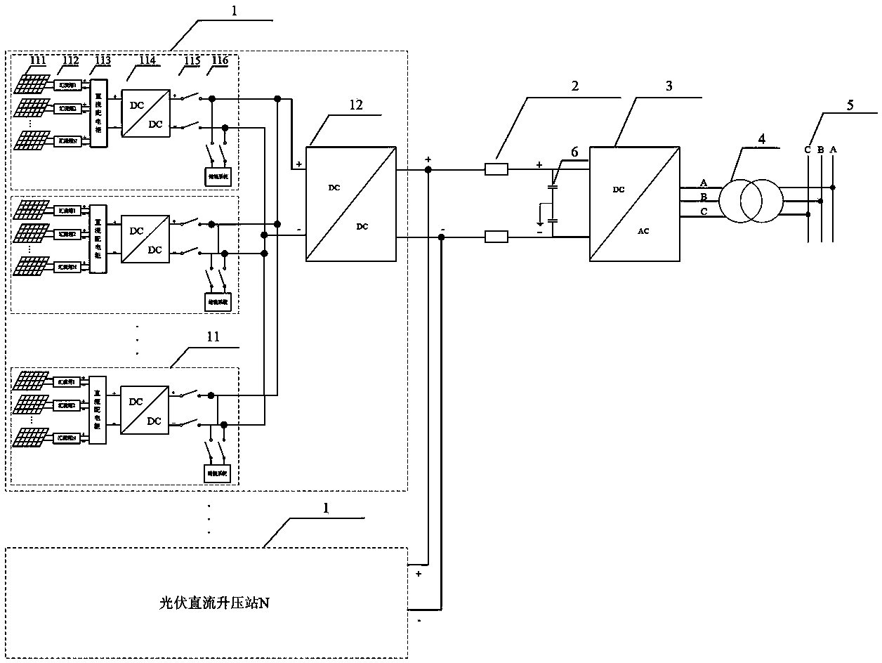
[0020] Such as figure 1 As shown, the high-voltage direct current transmission type grid-connected photovoltaic power generation system of the present invention includes more than one photovoltaic direct current booster station 1, high-voltage direct current transmission line 2, third-stage DC / AC converter 3, transformer 4, and high-voltage AC network 5. Photovoltaic DC boost station 1 is connected to the input end of the third-stage DC / AC converter 3 via the high-voltage direct current transmission line 2, and the output end of the third-stage DC / AC converter 3 is connected to the high-voltage AC network via the transformer 4 5 Connected. When there are more than two photovoltaic DC booster stations 1, the two or more photovoltaic DC booster stations 1 are connected in parallel.

[0021] Each photovoltaic DC boost station 1 includ...


PUM


Abstract

The invention discloses a high-voltage direct current transmission type grid-tied photovoltaic power generation system, which comprises more than one photovoltaic direct current booster station, a high-voltage direct current transmission line, a third-level DC/AC converter, a transformer and a high-voltage alternating current grid, the photovoltaic direct current booster stations are connected with the input end of the third-level DC/AC converter via the high-voltage direct current transmission line, and the output end of the third-level DC/AC converter is connected with the high-voltage alternating current grid via the transformer. The high-voltage direct current transmission type grid-tied photovoltaic power generation system has the advantages of simple and compact structure, low cost, convenience in installing and use, high efficiency, wide application range and the like.

Description

technical field [0001] The invention mainly relates to the field of photovoltaic power generation equipment, in particular to a high-voltage direct current transmission type grid-connected photovoltaic power generation system. Background technique [0002] With the continuous aggravation of the energy crisis and the increasingly serious climate and environmental problems, the development and utilization of new energy sources is imminent. The earthquake in Japan triggered a serious leak of nuclear radiation in Fukushima, which once again caused the world to reflect on the safety of nuclear power. Germany will shut down its last nuclear power plant in 2022; China has also re-assessed the safety of its planned new nuclear power plant. [0003] Followed by photovoltaic power generation, wind power and other renewable energy has received widespread global attention. In March 2009, "Implementation Opinions on Accelerating the Application of Solar Photovoltaic Buildings" and "Inte...

Claims


Application Information

Patent Timeline
IPC IPC(8): H02J3/38H02N6/00
CPCY02E10/563Y02E10/56
Inventor 冯江华李云蹇芳吴小云李建泉程宇旭姚明管仁德翟文杰崔坚
Owner CSR ZHUZHOU ELECTRIC LOCOMOTIVE RES INST
Why Eureka
Try Eureka