Electric deionization device for producing deionized water

A technology of electrodeionization and deionized water, applied in electrodialysis, separation methods, semi-permeable membrane separation, etc., can solve problems such as ineffective functioning

Active Publication Date: 2013-10-23
ORGANO CORP
View PDF8 Cites 4 Cited by
  • Summary
  • Abstract
  • Description
  • Claims
  • Application Information

AI Technical Summary

Problems solved by technology

[0018] Therefore, even when an attempt is made to prevent the transfer of carbonic acid and silica by using a cation exchange membrane in a low pH region, these molecules easily pass through the cation exchange membrane because the repulsion based on negative charges does not function effectively

Method used


Image

  • Electric deionization device for producing deionized water
  • Electric deionization device for producing deionized water
  • Electric deionization device for producing deionized water

Examples


Embodiment approach 1

[0035] One example of an embodiment of the electrodeionization apparatus for producing deionized water according to the present invention will be described with reference to the accompanying drawings.

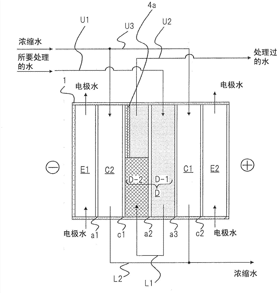
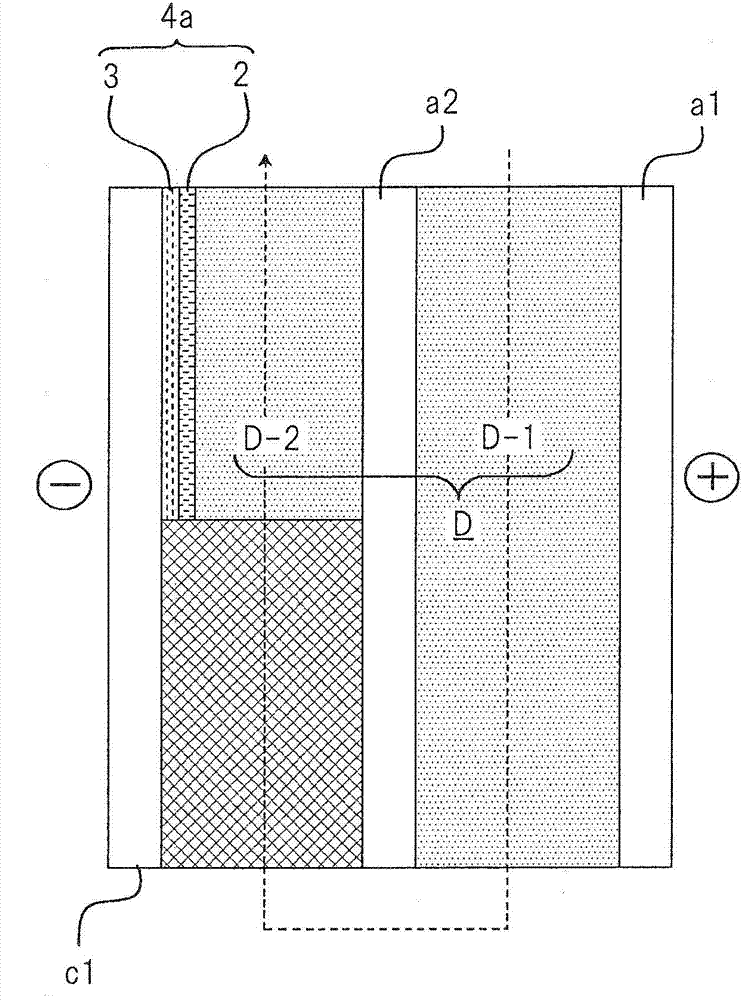
[0036] figure 1 is a diagram schematically showing the configuration of the deionized water production apparatus according to the present embodiment. exist figure 1 In the deionized water preparation device shown in , the deionization treatment unit is arranged between the cathode chamber E1 provided with the cathode and the anode chamber E2 provided with the anode. The deionization processing unit is composed of a deionization chamber D and a pair of concentrating chambers C1 and C2 disposed adjacent to the deionization chamber D on opposite sides thereof. In the following description, among the pair of concentrating chambers C1 and C2, the concentrating chamber C1 adjacent to the anode chamber E2 is referred to as "the first concentrating chamber C1", and the concentratin...

Embodiment approach 2

[0088] Another example of an embodiment of the electrodeionization apparatus for producing deionized water according to the present invention will be described with reference to the accompanying drawings. The deionized water production apparatus according to the present embodiment has the same configuration as the apparatus according to Embodiment 1 except that a plurality of deionization treatment units are disposed between the cathode chamber and the anode chamber. Therefore, only configurations different from the deionized water production apparatus according to Embodiment 1 will be described below. A description of the same configuration will not be made.

[0089] Figure 4 is a diagram schematically showing the configuration of the deionized water production apparatus according to the present embodiment. exist Figure 4 In the deionized water preparation device shown in , two deionized treatment units are arranged between the cathode chamber E1 and the anode chamber E2...

Embodiment approach 3

[0107] will refer to Figure 5 Yet another example of an embodiment of the deionized water producing apparatus according to the present invention is described. The deionized water production apparatus according to this embodiment has the same basic configuration as that according to Embodiment 2. Therefore, only the differences between the deionized water production apparatus of the present embodiment and the deionized water production apparatus of Embodiment 2 will be described below. Descriptions for the same points will not be repeated.

[0108] Such as Figure 5 As shown in , in the deionized water producing apparatus according to the present embodiment, the sub-deionization chamber S1 is disposed between the cathode chamber E1 and the second concentrating chamber C2. The sub-deionization chamber S1 is adjacent to the cathode chamber E1 with the sixth anion exchange membrane a6 interposed therebetween. The sub-deionization chamber S1 is adjacent to the second concentra...


PUM


Abstract

In order to enable the production of high-purity deionized water and inhibit scale formation, an electric device for producing deionized water is provided with at least one desalination treatment unit, said desalination treatment unit being provided between a cathode chamber (E1) and an anode chamber (E2), and being formed from a desalination chamber (D) and a pair of concentration chambers (C1, C2) which are provided on both sides of the desalination chamber (D) and into which an anion exchanger is filled. The desalination chamber (D) is partitioned, by an ion exchange membrane, into a first small desalination chamber (D-1) which is adjacent to one side of one of the concentration chambers (C1), and a second small desalination chamber (D-2) which is adjacent to the other concentration chamber (C2); the anion exchanger is filled into the first small desalination chamber (D-1), and the anion exchanger and a cation exchanger are filled into the second small desalination chamber (D-2) in an order such that the last ion exchanger through which the water which is undergoing treatment passes is the anion exchanger; and on the cathode side of the anion exchanger filled into the second small desalination chamber (D-2) a bipolar membrane (4a) is arranged in an orientation such that the anion exchange membrane surface thereof faces the anion exchanger.

Description

technical field [0001] The present invention relates to electrodeionization apparatus for producing deionized water and, more particularly, to the structure of a deionization chamber. Background technique [0002] Deionization devices are known for producing deionized water, in which the deionization takes place by passing the water to be treated through ion exchangers. In these production devices, when deionization performance decreases due to saturation of ion exchange groups, it is necessary to regenerate ion exchange groups in ion exchangers with chemicals such as acids or bases. More specifically, what is required is to use the acid-derived H + and OH from the base - Displaces anions and cations adsorbed to ion exchange bases. In recent years, an electrodeionization device for producing deionized water that does not require regeneration with chemicals has been developed and brought into practical use to overcome the operational drawbacks described above. [0003] An...

Claims


Application Information

Patent Timeline
Patent Type & Authority Applications(China)
IPC IPC(8): C02F1/469B01D61/46B01D61/48
CPCC02F1/4695C02F2201/46145C02F2103/04B01D61/445C02F2303/22C02F2001/46128Y02A20/124B01D61/48B01D61/422C02F2201/46
Inventor 长谷川一哉佐佐木庆介浅川友二
Owner ORGANO CORP
Why Eureka
Try Eureka