Bimetal composite pipe automatic butt welding equipment

A bimetal composite pipe and welding equipment technology, applied in welding equipment, welding equipment, auxiliary welding equipment, etc., can solve problems such as on-site welding defects, and achieve the effects of improving welding production efficiency, speeding up construction speed, and convenient operation

Active Publication Date: 2015-09-09
BC P INC CHINA NAT PETROLEUM CORP +1
View PDF7 Cites 0 Cited by
  • Summary
  • Abstract
  • Description
  • Claims
  • Application Information

AI Technical Summary

Problems solved by technology

The emergence of bimetallic composite pipes has greatly reduced the cost of high-corrosion-resistant pipes, but defects often occur in on-site welding, which has become a key factor limiting its popularization and application

Method used


Image

  • Bimetal composite pipe automatic butt welding equipment
  • Bimetal composite pipe automatic butt welding equipment
  • Bimetal composite pipe automatic butt welding equipment

Examples


Embodiment 1

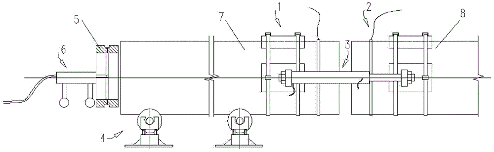
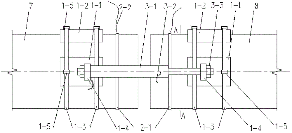
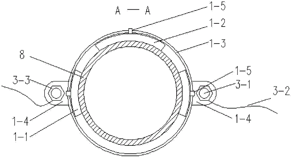
[0048] see Figure 14 , for the bimetallic composite pipe of small size outer diameter, its clamping steps: a. Place the movable bimetallic composite pipe 7 to be welded in the two concave rollers 4-6 of the support adjustment device 4, and rotate The handle 4-3 rotates the lead screw 4-2 to adjust the height, so that the axis of the movable bimetal composite pipe 7 to be welded is aligned with the axis of the static bimetal composite pipe 8 to be welded; b. At the end, two sets of arc-shaped side clamping plates 1-1 are symmetrically arranged on both sides of the outer diameter of the two tubes to be welded, and a set of arc-shaped upper clamping plates 1-2a are respectively arranged on the two tubes to be welded. Above the outer diameter of the welding end, that is, the movable bimetallic composite pipe 7 to be welded and the stationary bimetallic composite pipe 8 to be welded are equipped with three sets of clamping plates on the outer diameter of the adjacent pipe end, lef...

Embodiment 2

[0050] see Figure 15 , for bimetallic composite pipes with large outer diameters, the clamping steps: In order to ensure sufficient welding extrusion force, add a set of lower clamping plates 1-2b. In step b., the adjacent ends of the two pipes are arranged symmetrically on both sides of the outer diameter of the ends of the two pipes to be welded using two sets of arc-shaped side clamping plates 1-1 respectively, and two sets of arc-shaped side clamping plates are used respectively. The upper clamping plate 1-2a and the lower clamping plate 1-2b are arranged above and below the outer diameters of the ends of the two pipes to be welded, that is, the movable bimetallic composite pipe 7 to be welded and the static bimetallic composite pipe to be welded 8 The outer diameters of adjacent pipe ends are equipped with four sets of clamping plates, left, right, upper and lower, arranged evenly, and then the fastening belts 1-3 pass through the buckles 1-5 on the four sets of clamping...


PUM


Abstract

The invention discloses automatic butt welding equipment for bimetal composite pipes and belongs to the field of oil and gas pipelines. The equipment mainly comprises clamping devices, conducting devices, a hydraulic source connecting device, support adjusting devices, a ceramic ring, and an electric propulsion unit. A movable bimetal composite pipe to be welded is disposed on the support adjusting devices. The end, to be welded, of the movable bimetal composite pipe to be welded corresponds to the end, to be welded, of a fixed bimetal composite pipe to be welded. Horizontal center lines of the two pipes are coaxial. A set of clamping devices is disposed on the outer periphery of each of the butt-welded end of the movable bimetal composite pipe to be welded and the butt-welded end of the fixed bimetal composite pipe to be welded. The automatic butt welding equipment for bimetal composite pipes has the advantages that the bimetal composite pipe can be butt-welded on the site quickly and conveniently, weld defects are less, weld failure accidents are less, and the equipment is simple in structure, convenient to operate and faster for construction.

Description

technical field [0001] The invention relates to the field of petroleum and natural gas transmission pipelines, in particular to an automatic butt welding equipment for bimetal composite pipes. Background technique [0002] In the process of oil and gas extraction, corrosive media are often transported. As the demand for energy increases, more and more highly corrosive water-bearing crude oil or natural gas containing high sulfur or carbon dioxide is extracted, and the demand for high corrosion-resistant alloys is also increasing. However, due to the high price of high-corrosion-resistant alloys, it greatly affects the economic benefits of oilfield users. In order to reduce short-term investment costs, users are generally not willing to use high-performance corrosion-resistant alloy pipes, resulting in frequent pipeline corrosion failures. [0003] Bimetal composite pipe is a new type of wear-resistant pipe. The outer layer of the pipe is made of ordinary steel pipe, and the...

Claims


Application Information

Patent Timeline
Patent Type & Authority Patents(China)
IPC IPC(8): B23K9/16B23K37/053B23K101/06
Inventor 申昭熙胡美娟冯春王新虎王建军李磊
Owner BC P INC CHINA NAT PETROLEUM CORP
Why Eureka
Try Eureka