Method for manufacturing MEMS (Micro Electro Mechanical System) and MEMS inertial sensor

An inertial sensor and inertial technology, applied in the direction of using electric/magnetic devices to transmit sensing components, instruments, steering sensing equipment, etc., can solve problems such as difficulties and increased difficulty of integration technology

Active Publication Date: 2013-10-30
ZHEJIANG JUEXIN MICROELECTRONICS CO LTD
View PDF6 Cites 27 Cited by
  • Summary
  • Abstract
  • Description
  • Claims
  • Application Information

AI Technical Summary

Problems solved by technology

[0008] However, it is also very difficult to manufacture capacitive inertial sensors on semiconductor substrates including CMOS ROIC, especially the thin-layer silicon substrate technology compatible with CMOS chip technology is widely used, which makes this integration technology more difficult

Method used


Image

  • Method for manufacturing MEMS (Micro Electro Mechanical System) and MEMS inertial sensor
  • Method for manufacturing MEMS (Micro Electro Mechanical System) and MEMS inertial sensor
  • Method for manufacturing MEMS (Micro Electro Mechanical System) and MEMS inertial sensor

Examples


Embodiment Construction

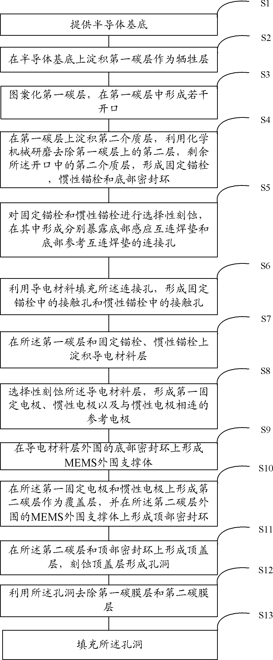
[0082] In order to make the above objects, features and advantages of the present invention more comprehensible, specific implementations of the present invention will be described in detail below in conjunction with the accompanying drawings.

[0083] In the following description, specific details are set forth in order to provide a thorough understanding of the present invention. However, the present invention can be implemented in many other ways than those described here, and those skilled in the art can make similar extensions without departing from the connotation of the present invention. Accordingly, the present invention is not limited to the specific embodiments disclosed below.

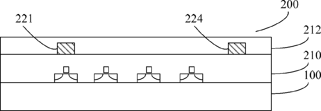
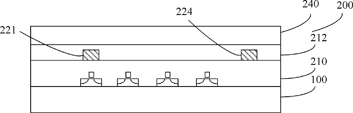
[0084] Considering the shortcomings of the prior art, in order to measure the horizontal or vertical movement of the inertial electrode relative to the carrier, it is necessary to use a thin-film manufacturing process to set one or more separate inertial electrodes and fixed electrodes, and...


PUM


Abstract

The invention provides a method for manufacturing a MEMS (Micro Electro Mechanical System) and an MEMS inertial sensor. The method comprises the steps of depositing a first carbon layer serving as a sacrificial layer on a semiconductor substrate; patterning the first carbon layer and forming a fixed anchor bolt, an inertial anchor bolt and a bottom sealing ring; forming a contact plug in the fixed anchor bolt and a contact plug in the inertial anchor bolt; forming a first fixed electrode, an inertial electrode and a connection electrode connected with the inertial electrode on the first carbon layer, the fixed anchor bolt and the inertial anchor bolt, wherein the first fixed electrode and the inertial electrode form a pair of capacitors; forming second carbon layers serving as covering layers on the first fixed electrode and the inertial electrode; and forming top cover layers on the second carbon layers and a top sealing ring. According to the inertial sensor provided by the invention, under the action of the inertial force, only the inertial electrode moves and the fixed electrode can not move or vibrate, so that the accuracy of the inertial sensor is improved.

Description

technical field [0001] The invention relates to an inertial sensor and a manufacturing method thereof, in particular to a silicon-based capacitive micro-mechanical structure (MEMS) inertial sensor. Background technique [0002] MEMS devices usually include single and composite micromechanical structures, which not only have electrical functions, but also have mechanical, optical, chemical and biological functions. MEMS devices and semiconductor integrated circuits can achieve certain functions as an integrated system. MEMS devices are commonly used in sensors, control systems, or to drive mechanical, optical, or chemical motions in tiny areas, either as stand-alone units or as a system. There is a type of MEMS device or system that is widely used to measure inertial force through translation, rotation motion or inertial sensing, such as MEMS acceleration sensors and gyroscopes. [0003] The existing capacitive MEMS inertial sensors all include a pair of inertial electrodes ...

Claims


Application Information

Patent Timeline
Patent Type & Authority Applications(China)
IPC IPC(8): B81C1/00G01D5/241
CPCB81C1/00134B81B3/0018G01C19/5783G01P15/00G01C19/56B81B2201/025B81C1/00293B81C2203/0145G01P15/125
Inventor 王志玮唐德明张镭毛剑宏韩凤芹
Owner ZHEJIANG JUEXIN MICROELECTRONICS CO LTD
Why Eureka
Try Eureka