
Dynamic compactor capable of quickly releasing rope

A dynamic tamping machine, fast technology, applied in soil protection, construction, infrastructure engineering, etc., can solve the problems that the speed of steel wire rope can not reach the speed of free fall, increase workload, splash of gravel, etc., to achieve great practicality and promotion value, reduce labor intensity, and facilitate the effect of quick and easy slipping

Inactive Publication Date: 2013-10-30
山西兴跃建设工程有限公司
View PDF7 Cites 2 Cited by
  • Summary
  • Abstract
  • Description
  • Claims
  • Application Information

AI Technical Summary

Problems solved by technology

During the construction process of this kind of equipment, the rammer needs to be decoupled by the decoupling device every time the rammer falls to the ground. After the rammer falls to the ground, the rammer is hooked by the decoupling device to perform lifting and repeated work; Although the tamping effect on the foundation is achieved, due to the structure of the existing hoist, when the rammer falls, the speed of the steel wire rope is far from the speed of the free fall, so the only way to separate the rammer from the uncoupling device is to use the decoupling method. , so as to tamp
Since the tamper has to be re-hooked and unhooked after landing, a large workload has been increased. At the same time, due to the splashing of gravel during the construction process, there are great safety hazards in the construction process. Some dynamic tamping machines are improved to improve work efficiency and construction safety

Method used


Image

  • Dynamic compactor capable of quickly releasing rope
  • Dynamic compactor capable of quickly releasing rope
  • Dynamic compactor capable of quickly releasing rope

Examples


Embodiment Construction

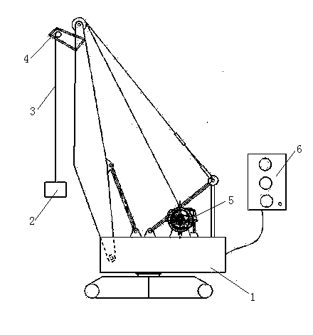
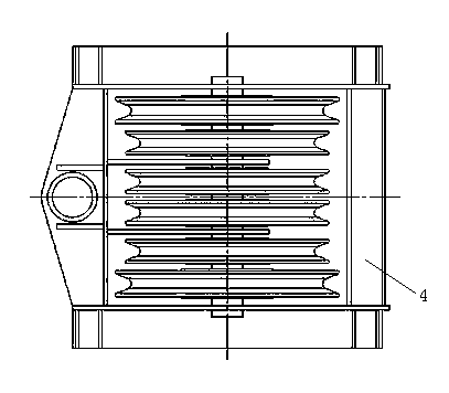
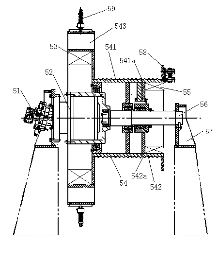
[0020] Refer to attached figure 1 , attached figure 2 , attached image 3 , a fast rope-releasing dynamic tamping machine of the present invention, which is composed of a frame 1, a rammer 2, a steel wire rope 3, a pulley mechanism 4, a hoist 5, and a control component 6. The frame 1 can be a crawler-type mobile vehicle Body, tower frame, "L" type frame wherein a kind of structural form, the frame 1 of present embodiment is the structural form of crawler type mobile car body, rammer 2 is arranged on the pulley mechanism 4 by steel wire rope 3; Wire rope 3 links to each other with winch 5 through pulley mechanism 4, and described pulley mechanism 4 is the rope-releasing mechanism of a multi-group fixed pulley structure; Described control part 6 is used for controlling the work of complete machine and winch 5; Described winch 5 is a fast unwinding rope winding mechanism with a main reel 541 and an auxiliary reel 542 that can rotate simultaneously and rotate separately. And t...


PUM


Abstract

The invention relates to a dynamic compactor capable of quickly releasing a rope. The dynamic compactor comprises a framework, a tamper, the steel wire rope, a pulley mechanism, a winch and a control component. The tamper is arranged on the pulley mechanism via the steel wire rope; the steel wire rope is connected with the winch by the pulley mechanism; the control component is used for controlling operation of the integral dynamic compactor and operation of the winch; the winch is a quick rope releasing winding and unwinding mechanism, the quick rope releasing winding and unwinding mechanism comprises a main winding drum and an auxiliary winding drum, and the main winding drum and the auxiliary winding drum can rotate simultaneously or respectively. The dynamic compactor has the advantages that the winch is in a quick rope releasing structural form, so that the main winding drum can rotate when the rope is released, and purposes of quickly releasing the rope and enabling the tamper to quickly descend are achieved; an internal expansion clutch is arranged in the auxiliary winding drum, so that twining of the steel wire rope is prevented; the pulley mechanism is in a form with a plurality of groups of fixed pulley structures and brings convenience for quickly releasing the steel wire rope in a humping manner; the tamper is connected with the steel wire rope after descending, the tamper re-hooking time is shortened in a construction procedure, and the labor intensity is reduced.

Description

technical field [0001] The invention relates to dynamic ramming construction equipment in civil engineering, in particular to a fast rope-releasing dynamic ramming machine. Background technique [0002] After retrieving the relevant patent documents, no fast rope-releasing dynamic tamping machine with the same structure as the present invention has been retrieved at present. In the process of dynamic compaction construction in existing civil works, hoists or hydraulic equipment are generally used to lift the rammer to a specified height, and then release the rammer through the uncoupling device, and use the energy generated by the rammer to fall by itself to form a strong impact on the foundation, so as to achieve The purpose of tamping the foundation. During the construction process of this kind of equipment, the rammer needs to be decoupled by the decoupling device every time the rammer falls to the ground. After the rammer falls to the ground, the rammer is hooked by the...

Claims


Application Information

Patent Timeline
IPC IPC(8): E02D3/054
Inventor 娄兴建丁邦建吕庆桃马云骄
Owner 山西兴跃建设工程有限公司
Features
  • Generate Ideas
  • Intellectual Property
  • Life Sciences
  • Materials
  • Tech Scout
  • Unparalleled Data Quality
  • Higher Quality Content
  • 60% Fewer Hallucinations
Learn More