Transversely-arranged high-current electron beam cross section three-dimensional scanning measurement system

A measurement system and three-coordinate technology, applied in the direction of current density measurement, etc., can solve the problems of costing manpower, material resources, measuring the transmission characteristics of the entire electron beam, and being unusable, etc., and achieve the effect of small size

Inactive Publication Date: 2013-10-30
INST OF ELECTRONICS CHINESE ACAD OF SCI
View PDF4 Cites 6 Cited by
  • Summary
  • Abstract
  • Description
  • Claims
  • Application Information

AI Technical Summary

Problems solved by technology

[0003] First, it cannot be connected to a large-scale high-current electron beam analyzer as a component, and it is also difficult to measure the entire transmission characteristics of the electron beam in the focused state of the electromagnetic field.
[0004] Second, in the measurement work, three vacuum stepping motors control the Faraday cylinder extending into the high vacuum cavity to scan a certain section of the electron beam, and use its inner cylinder in the pinhole to collect the current passing through the pinhole and Pull out the amplification, record the current intensity at a certain pinhole position, and further cooperate with the three stepping motors to make the Faraday cylinder scan different sections of the electron beam to obtain the entire electron beam configuration and current density distribution on

Method used


Image

  • Transversely-arranged high-current electron beam cross section three-dimensional scanning measurement system
  • Transversely-arranged high-current electron beam cross section three-dimensional scanning measurement system
  • Transversely-arranged high-current electron beam cross section three-dimensional scanning measurement system

Examples


Embodiment Construction

[0028] In order to make the object, technical solution and advantages of the present invention clearer, the present invention will be further described in detail below in conjunction with specific embodiments and with reference to the accompanying drawings.

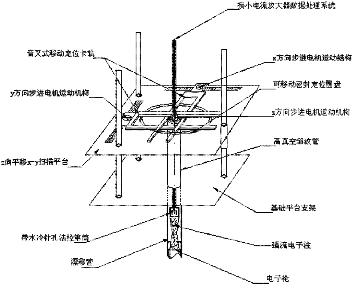
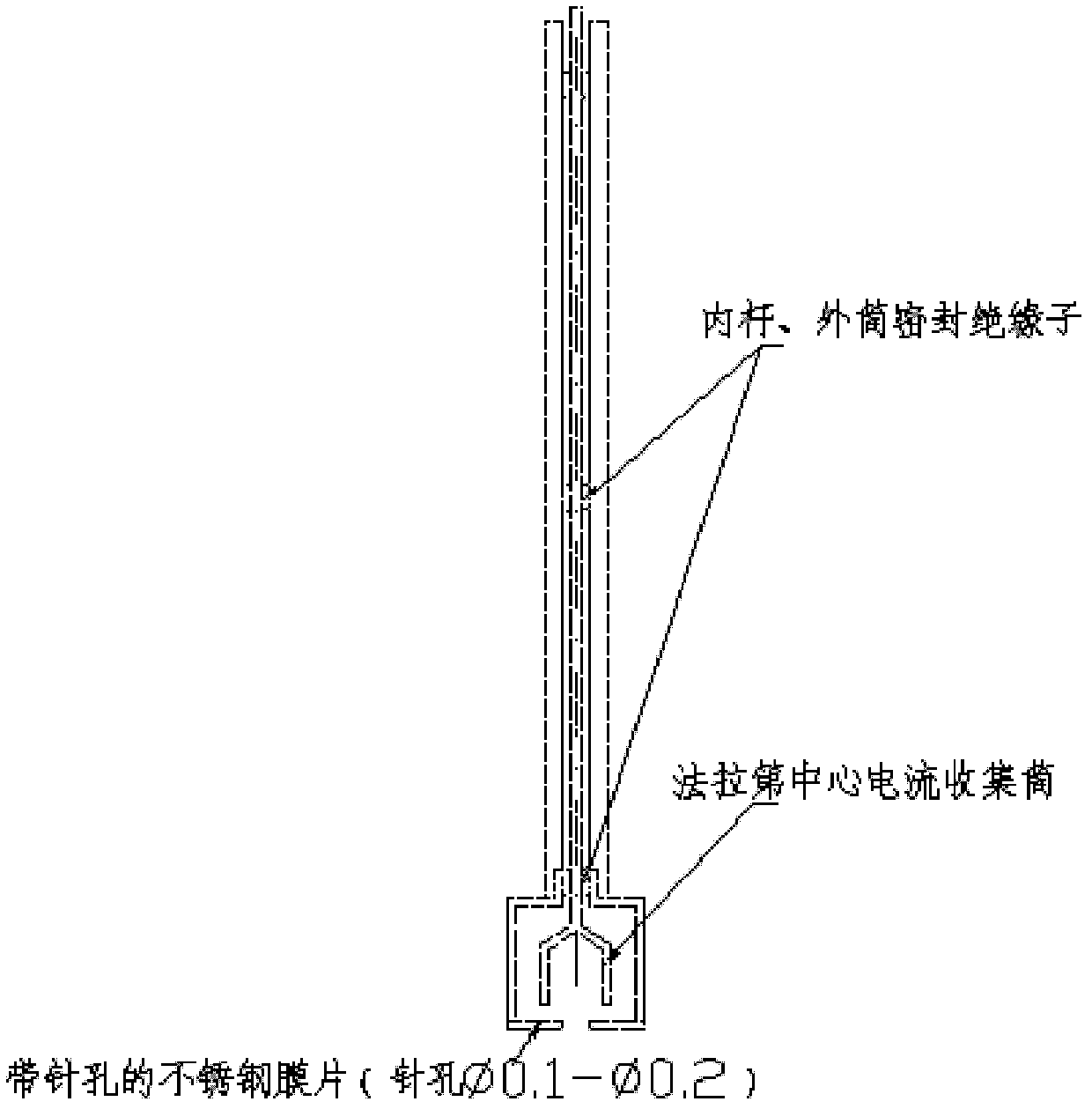
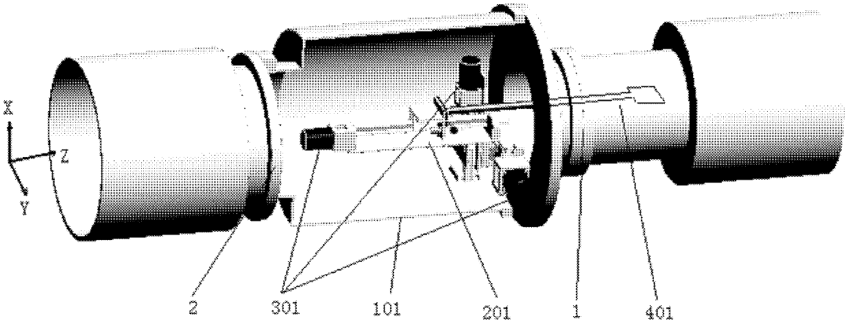
[0029] image 3 It is a structural schematic diagram of the three-coordinate scanning measurement system for the high-current electron beam section of the present invention, Figure 4 It is a schematic diagram of the X-Y cross-sectional structure of the three-coordinate precision platform of the present invention, Figure 5 It is a structural schematic diagram of the water-cooled Faraday cage of the present invention. Depend on image 3 , Figure 4 , Figure 5 It can be seen that the three-coordinate scanning measurement system of the high-current electron beam section of the present invention includes a measurement work area cavity 101, the cavity 101 includes an observation window, a low-voltage feed head 3, a front...


PUM


Abstract

The invention discloses a transversely-arranged high-current electron beam cross section three-dimensional scanning measurement system which comprises a measurement working area cavity and a Faraday cylinder sensor system. A high-vacuum movement mechanism is arranged inside the measurement working area cavity and comprises a high-vacuum three-dimensional mobile platform and a high-vacuum stepping motor. The Faraday cylinder sensor system comprises a Faraday cylinder sensor formed by an outer Faraday cylinder and an inner Faraday cylinder. A Faraday cylinder sensor support rod is fixed on the high-vacuum movement mechanism and can be moved and positioned in three directions through driving of the high-vacuum movement mechanism. The transversely-arranged high-current electron beam cross section three-dimensional scanning measurement system is small in size, can be longitudinally used separately, can serve as a part transversely arranged and connected into a large transverse high-current electron beam analysis meter to be used and can measure the whole-course transmission characteristics of a high-current electron beam under focusing of an electromagnetic field. In addition, the transversely-arranged high-current electron beam cross section three-dimensional scanning measurement system can measure the electronic optical performance of the high-current electron beam with current magnitude ranging from hundreds of volts to about hundred thousands of volts and meanwhile can further provide a beneficial calibration reference method for other quick high-voltage high-current electron beam measurement methods, such as an X-ray braking radiation method.

Description

technical field [0001] The invention relates to a measurement system for a high-current electron beam analyzer, in particular to a three-coordinate scanning measurement system for a cross-section of a high-current electron beam arranged laterally. Background technique [0002] figure 1 It is a schematic diagram of the structure of the traditional high-current electron beam cross-section three-coordinate scanning measurement system, figure 2 It is a schematic diagram of the structure of a traditional Faraday cage. Depend on figure 1 with figure 2 It can be seen that the traditional three-coordinate scanning measurement system of the high-current electron beam cross-section is vertically erected, and its three-dimensional motion platform and precision guide rails are all set outside the high-vacuum chamber. Its disadvantages are: [0003] First, it cannot be connected to a large-scale high-current electron beam analyzer as a component, and it is also difficult to measur...

Claims


Application Information

Patent Timeline
IPC IPC(8): G01R19/08
Inventor 吴迅雷阮存军李庆生李崇山李彦峰
Owner INST OF ELECTRONICS CHINESE ACAD OF SCI
Why Eureka
Try Eureka