Method for controlling NPC three-level inverter fault redundancy
A three-level inverter and redundant control technology, which is applied to electrical components, AC power input conversion to DC power output, output power conversion devices, etc., can solve the problem of increased hardware costs and insufficient use of multi-level Inverter software control method redundancy characteristics, complex system structure and other issues, to achieve the effect of improving reliability
- Summary
- Abstract
- Description
- Claims
- Application Information
AI Technical Summary
Problems solved by technology
Method used
Image
Examples
Embodiment 1
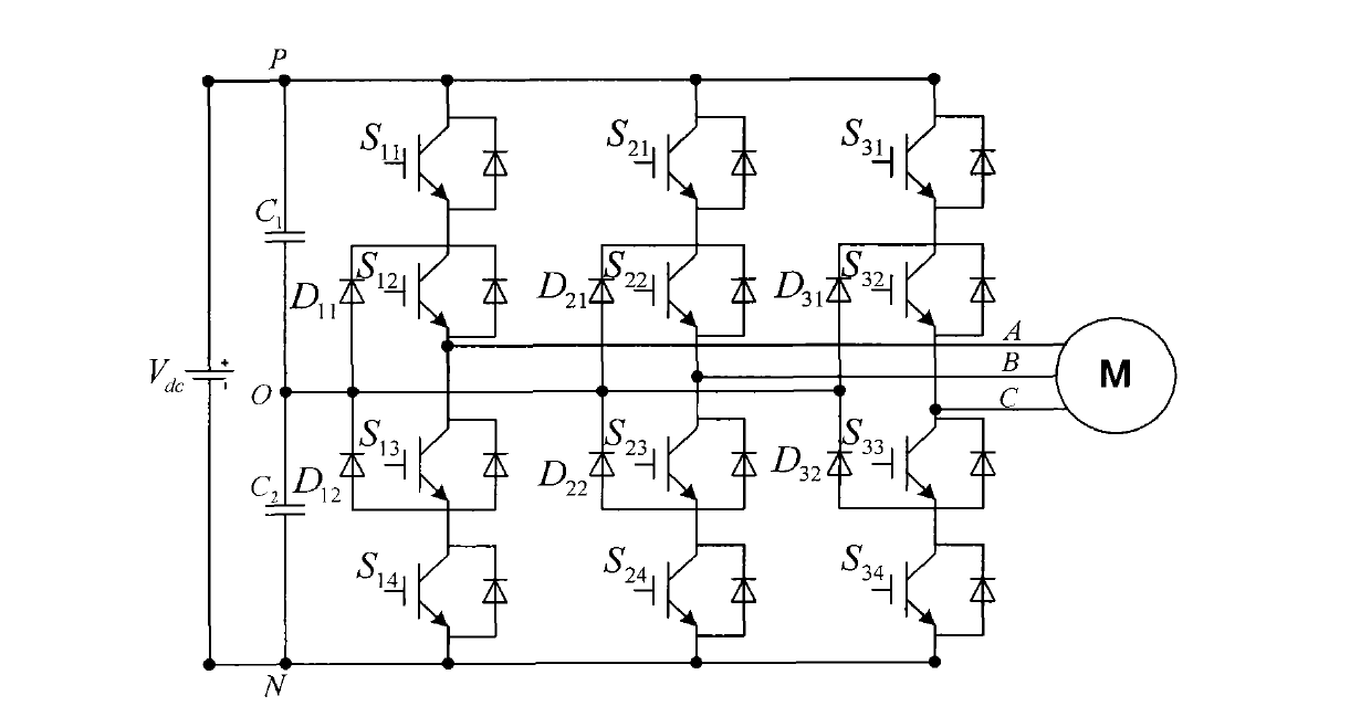
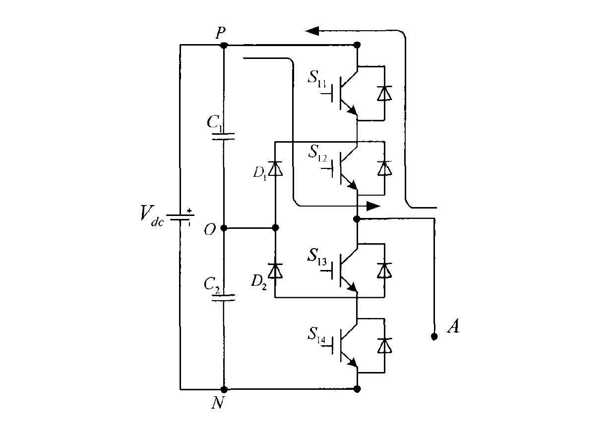
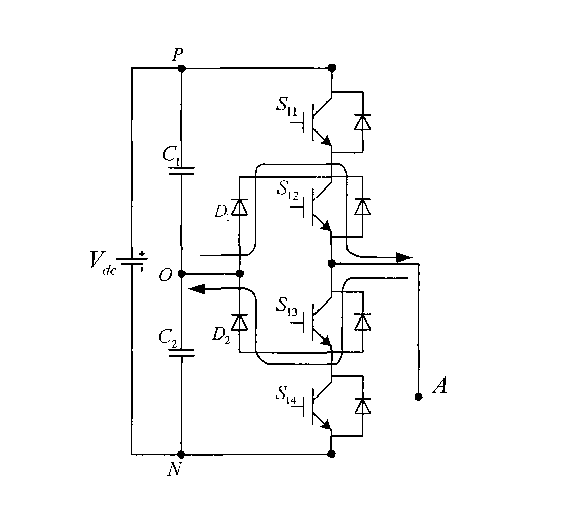
[0056] Embodiment 1: Real-time monitoring of device faults is performed on the NPC three-level inverter. When the device S is detected 11 When the terminal voltage is always zero, S 11 If a short-circuit fault occurs in the tube, if the phase A of the inverter is still output at the O level state, it will cause the capacitor C 1 short circuit, therefore, S 11 After a short-circuit fault occurs in the tube, the A phase can only output the two level states of P and N, and cannot output the O level state. Image 6 is the space voltage vector distribution diagram in the fault state, and the double dashed line in the figure is the fault loss vector. The vectors lost after phase A loses the O level state include zero vectors (OOO), small vectors (ONO, ONN, OON, OPO, OPP, OOP) and medium vectors (OPN, ONP). observe Image 6 It can be seen that both the lost zero vector and the small vector have redundant vectors, and the medium vectors lost in the second and fifth sectors have no...
Embodiment 2
[0060] Embodiment 2: Real-time monitoring of device faults is performed on NPC three-level inverters. When a device S is detected 11 When the terminal voltage of S is always non-zero, S 11 An open-circuit fault occurs in the tube, and at this time, the phase A of the inverter cannot output the P level state. Therefore, the S 11 After a short-circuit fault occurs in the tube, the A phase can only output two levels of O and N. Figure 7 It is the space voltage vector distribution diagram in the fault state, the double dashed line in the figure is the fault loss vector, the loss vector after the A phase loss P state includes zero vector (PPP), small vector (PPO, POO, POP) , medium vector (PON, PNO) and large vector (PPN, PNN, PNP). In the vector diagram, both the lost zero vector and the small vector have redundant vectors; in the first and sixth sectors, the lost medium vector has no redundant vectors; in the first, second, fifth, and sixth sectors, the lost large vector has n...
Embodiment 3
[0063] Embodiment 3: Real-time monitoring of device faults for NPC three-level inverters, when the device S is detected 12 When the terminal voltage of S is always zero, S 12 If a short-circuit fault occurs in the tube, if the A phase of the inverter is still output at the N level state, it will cause the capacitance C 2 short circuit, therefore, S 12 After a short-circuit fault occurs in the tube, the A phase can only output two level states of P and O, and cannot output the N level state. Figure 8 It is the space voltage vector distribution diagram in the fault state, the double dashed line in the figure is the fault loss vector, and the loss vector after the A phase loses the N state includes zero vector (NNN), small vector (NON, NOO, NNO) , medium vector (NPO, NOP) and large vector (NPN, NPP, NNP). In the vector diagram, both the lost zero vector and the small vector have redundant vectors; in the third and fourth sectors, the lost medium vector has no redundant vector...
PUM
 Abstract
Description
Claims
Application Information
 - R&D
- Intellectual Property
- Life Sciences
- Materials
- Tech Scout
- Unparalleled Data Quality
- Higher Quality Content
- 60% Fewer Hallucinations
Browse by: Latest US Patents, China's latest patents, Technical Efficacy Thesaurus, Application Domain, Technology Topic, Popular Technical Reports.
© 2025 PatSnap. All rights reserved.Legal|Privacy policy|Modern Slavery Act Transparency Statement|Sitemap|About US| Contact US: help@patsnap.com


